Control DC and Stepper Motors With L298N Dual Motor Controller Modules and Arduino

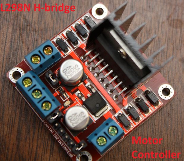
You don’t have to spend a lot of money to control motors with an Arduino or compatible board. After some hunting around we found a neat motor control module based on the L298N H-bridge IC that can allows you to control the speed and direction of two DC motors, or control one bipolar stepper motor with ease.The L298N H-bridge module can be used with motors that have a voltage of between 5 and 35V DC. With the module used in this tutorial, there is also an onboard 5V regulator, so if your supply voltage is up to 12V you can also source 5V from the board. So let’s get started!

Source: Control DC and Stepper Motors With L298N Dual Motor Controller Modules and Arduino

Control DC and Stepper Motors With L298N Dual Motor Controller Modules and Arduino was last modified: July 13th, 2017 by Jovan Stosic

Wiznet W5100 (Ethernet Shield) Buffer Question.

So it looks like there is 8Kb of internal RX buffer on the W5100 chip… so how does one deal with reading the data faster than its coming in?  If I don’t read it fast enough or too fast what happens?   How do you flush the buffer on chip via client.flush()?  I suspect it’s FIFO.   I’m running into a situation where I am getting 8k of data posted to me and it looks like the data is being “clipped” … guess the buffer is getting filled.Looking at the W5100.c file there is mention of how the memory channels are allocated…  anyone know how it’s setup to work?  Full 8kb or less?

Source: Wiznet W5100 (Ethernet Shield) Buffer Question.

Wiznet W5100 (Ethernet Shield) Buffer Question. was last modified: July 13th, 2017 by Jovan Stosic

Arduino Modules – L298N Dual H-Bridge Motor Controller

Quick and simple start guide for using and exploring an L298N Dual H-Bridge Motor Controller module with an Arduino.The model in the example I am using is from Ebay. Materials needed: L298N Dual H-Bridge Motor Controller module (various models will work) Male to Female jumper wires An Arduino, any flavor. A DC power supply, 7-35vA motor that is the correct voltage for your power supply used.

Source: Arduino Modules – L298N Dual H-Bridge Motor Controller

Arduino Modules – L298N Dual H-Bridge Motor Controller was last modified: July 13th, 2017 by Jovan Stosic

DIY Stepper Controller using Arduino | Night Sky in Focus

My first version of a stepper controller uses a 555 timer chip and a 74LS194 shift register. The tracking rate is controlled by the 555 timer chip through a resistor and a capacitor. By changing the resistance and capacitance values, the tracking rate also changes. A variable resistor is used to speed up and slow down the rotation of the stepper. Since the timing signals are controlled by analog components, the tracker suffers from issues related to the tracking rate. It usually requires ‘tracking rate adjustment’ (to match the movement of the sky) at the start of an imaging session. While it has served me for four years and used it to image some interesting targets, it is clear that an upgrade is needed.

Upon learning some basics about Arduino, I immediately saw the potential to use it as a controller for a stepper motor, the kind of motor used in devices that require precise motion control such as in many telescope mounts. I started looking at some excellent tutorials on the Internet and was able to build the simple stepper controller featured in this article.

The main advantage of using a microcontroller is that it makes it possible for the stepper controller to keep a far accurate tracking rate, unlike my previous controller that changes tracking rate with the slightest change in ambient temperature. Since it is digital, there is no need for a re-calibration at the start of every imaging session. Buttons can be placed to allow easy adjustment of the tracking speed such as to speed up or slow down the tracking rate momentarily, for easy adjustment. LEDs can be used as status indicators (e.g., current step rate).

After a few months, I have finally built a fairly simple yet reliable stepper controller that can be used to drive very small trackers, or even more advanced ones such as a telescope. And since it is built with an Arduino, it is possible to add some upgrades to it in the future.

arduino stepper

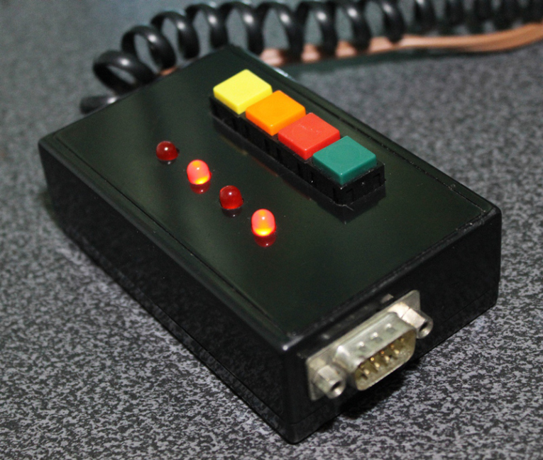
Controller for equatoral trackers such as a telescope mount with stepper motor

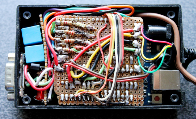
Removing the cover reveals the circuit board for the stepper driver. This circuit sits on top of the Arduino, much like a DIY shield (a circuit board that you can attach readily to an Arduino by stacking it on top of it, through the connecting pins.)

arduino_stepper (4)

Stepper controller with the DIY stepper driver circuit.

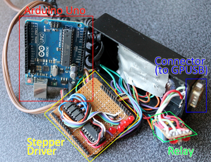
Dismantled, you can clearly see the Arduino board on the left (there are many versions of an Arduino board, in this particular project, I have used what is called an Arduino UNO). You can see the connecting pins that run vertically on the board’s left and right sides. The pins connect the Arduino to the Stepper Driver (center). The Stepper Driver is a board that holds L293D chip and some PC817 optical isolators. Some LED lights were left on the board which could come handy during troubleshooting. Also visible is some sort of a relay circuit and its connector (right), to allow a GPUSB (some kind of a module that allows a computer to talk to my telescope mount) to control the DIY Stepper Controller for autoguiding purposes (it’s a completely optional feature that I decided to include as it may come handy in the future). The use of a GPUSB, however, will be discussed in a separate article.

arduino_stepper (3)

Components of the stepper controller. Only the Arduino Uno and the Stepper driver will be discussed in this article. The Relay and the Connector (for GPUSB) to enable a computer to send guiding signals to the stepper controller (for autoguiding purposes) will be discussed in a separate article.

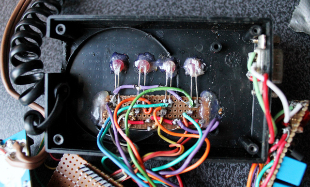
Here you can see the circuit board for the LED lights and the four push-button switches.

arduino_stepper (1)

The circuit for the LED lights and the push-buttons.

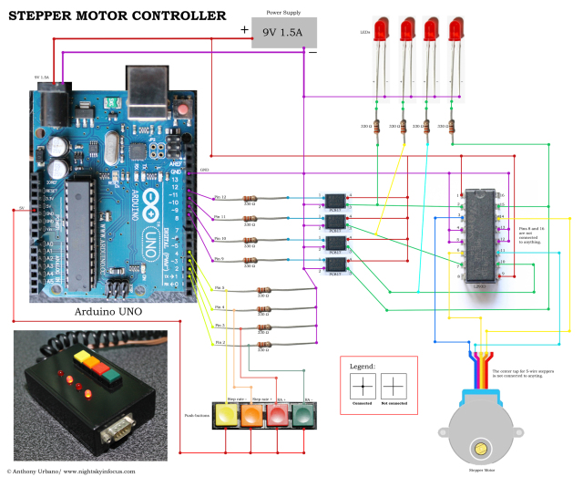
To build this DIY Stepper Controller, you will be needing some basic understanding of electronic circuits. The diagram below illustrates how the parts will be put together.

eteny_arduino_stepper_feb2016

To view a larger image, click here. Circuit diagram for the Stepper Motor Controller. An Arduino Uno is used to provide pulses for the L293D H-bridge through optional PC817 opto-isolators. The circuit can drive both bipolar and unipolar steppers (operated in bipolar mode).

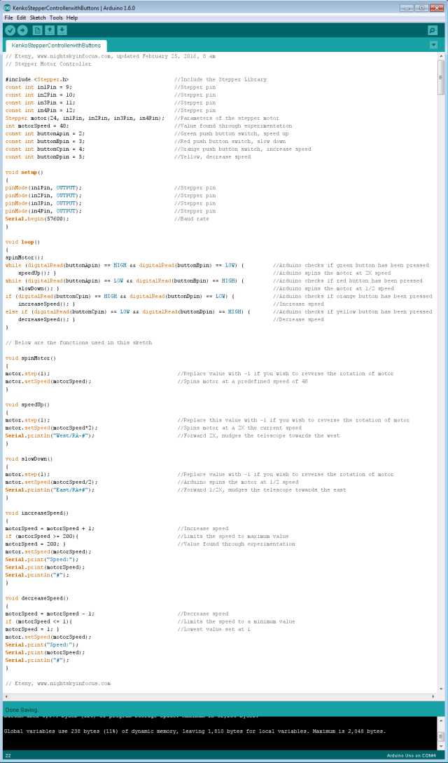
The Arduino board requires what is called a ‘sketch’. A screenshot of the sketch used in this DIY stepper controller is shown in the following photo. As you may have noticed, it is composed of lines of text with a set of instructions in it. It is a ‘program’ that you upload to the Arduino board to let it know what to do. This program is uploaded by connecting the Arduino board to a computer through a USB connection, using the Arduino Software. Learn more about Arduino. Once you are familiar with some basics, you will be able to understand how to use the sketch below.

Eteny_ControllerforKenkoNESmount

To view a larger image, click here. Script for the Arduino stepper motor controller. For inquiries about the sketch, please send an email to eteny@nightskyinfocus.com.

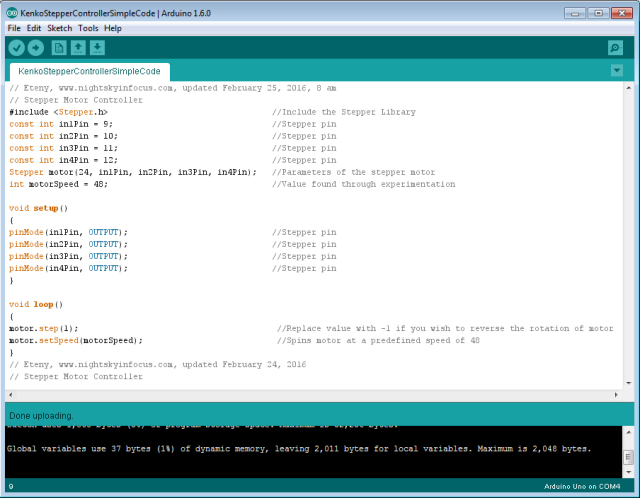
If the sketch above seems too complicated, you can try uploading a simpler sketch that can be used to spin the motor (note that this sketch does not read the buttons, it only spins the motor).

Eteny_simplecodeforKenkoNESmount

To view a larger image, click here. Script for the Arduino stepper motor controller. For inquiries about the sketch, please send an email to eteny@nightskyinfocus.com.

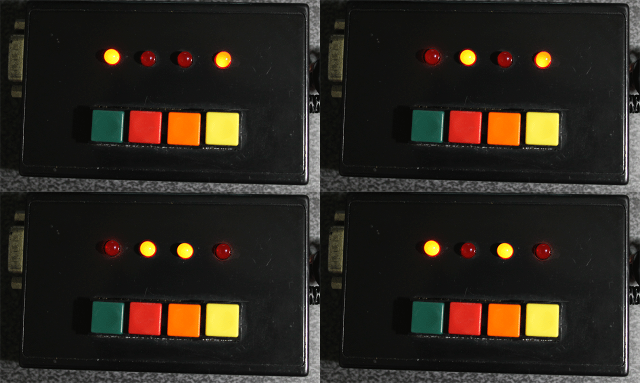
Once you’ve finished building the DIY Stepper Controller circuit above and uploaded the sketch to the Arduino board, you should see some blinking lights indicating that your controller is up and running and ready to track the skies!

arduino_stepper_lights

Arduino stepper motor controller for a telescope mount.

This page is a work-in-progress. In future posts, I will describe an advanced application of the tracker such as enabling the Arduino stepper controller to receive commands from a computer through a serial connection, and perform automatic tracking error corrections (autoguiding) with a program running on a computer, such as PHD Guiding.

Visit this page for captured images and future upgrades on this project. Clear skies!

test_shot_autoguider_moodedDSLR

To view a larger image, click here. A 240-second test image to determine the tracker’s accuracy. The image was taken a focal length of 900 mm from a city with severe light pollution using a filter-modified Canon 450D DSLR. Tracking was guided using PHD2 Guiding software, a modified Logitech 4000 web camera, and a 400 mm focal length guide scope.

Related link:
Stepper Motor Controller (Analog)
Improvised Clock Drive Project

Source: DIY Stepper Controller using Arduino | Night Sky in Focus

DIY Stepper Controller using Arduino | Night Sky in Focus was last modified: July 13th, 2017 by Jovan Stosic

Motors

This is a primer on electric motors, especially small DC motors. The information is for those who might want to know more about how the characteristics of the motor are related to the driving of a telescope and how the behavior of the motor might be affected by the type of electronic circuit used to drive it.  The discussion is rather long and complex but it must be to cover the nuances of DC motor operation which are so important for some aspects of telescope operation.

Small DC motors have many favorable characteristics.  They are very reliable, very strong for their size and very inexpensive. They can also be made to run on low voltages, have good electrical to mechanical conversion coefficients and are available in a immense variety of sizes and formats. They are thus used in many applications where the voltages available are only a few volts to a dozen volts. They have basic characteristics, which I will be describing, that are the result of physical and electrical laws. (No amount of advertising will change the laws of physics.) (though some will try)

The DC motor can be thought of as transducer which changes voltage and current into speed and torque.  That is, electrical power into mechanical power.  In the DC motor the current controls the force (or torque) and the voltage tends to control the speed. This is because of the basic relations,

  FORCE = (current) X (magnetic field)
VOLTAGE = (constant) X (time rate of cutting magnetic flux)

For our purposes the constant and the magnetic field term can be considered constants which depend on the design of the motor.  That is, such factors as the magnetic field strength the number of turns of wire etc.  We do not need to know more about the details of the design to understand the basic behavior of the motors.  We will use measured values for specific motors as examples later in this presentation.

The speed of the motor is quite proportional to the applied voltage. The reason is that the rotation of the motor creates a back voltage which counteracts the applied voltage.  When these two voltages are quite different there is a substantial current through the motor which causes considerable force (torque) and the motor speeds up until the back voltage is closer to the applied voltage. When the back voltage gets quite close to the applied voltage, the current becomes smaller and the torque decreases.  The motor runs at a speed where all these factors are in balance. That is, where the electrical power delivered to motor is about equal to the power absorbed by the load.  Because of the resistance of the windings in the motor some power is lost to heat.  So the electrical power exceeds the mechanical power by some amount.  In large motors the efficiency can be well over 90%.  In very small DC motors, the efficiency might be as low as 50%.

From this behavior we see that to control the speed of the motor, the voltage applied to the motor should be controlled.  When this is done the stability of  the motor shaft speed is stable.  If the motor is loaded mechanically it slows down, the back voltage decreases and the current increases thus increasing the torque to handle the higher load. This mode of operation is generally used when the load is light and the motor shaft is turning rapidly.

The torque of the motor is proportional, as seen from the basic equations, to the current through it.  If a fixed current is applied, to the motor it tends to yield a fixed torque.  If the mechanical torque is greater than that available from the motor, the motor stalls.  If the motor has excess torque it accelerates the load.  Eventually the back voltage will become great enough to modify the current to the motor.  But this will not happen rapidly because a current source, i.e. one with high resistance does not like to have its current change. It will resist the change until the value of the internal voltage is reached.

The point is that the value of the current is critical. Too little current, no motion, the motor stalls.  Too much current and the motor tends to run up to an excess speed.  Current and the torque it produces are very important when the motor is operating and very slow speed somewhere near stalled operation in a mechanical system.  This is particularly true for systems with significant stiction. (STICTION is the tendency of mechanical loads to require starting forces that are larger than running forces.  Most mechanical system have significant stiction.)

The above is actually slightly more complicated because any voltage is applied to the motor through some resistance. The resistance of the motor itself is a part of the total resistance and the resistance of the source voltage is the other part.  The source resistance is called “the source resistance.” (surprise) (The Thevenin resistance to EEs) The motor resistance results in heating of the motor and is thus kept as small as possible within the design parameters of the motor.  The voltage and current supplied to the motor can be easily measured. The speed and the torque of the motor can also be measured if suitable instruments are available. (I made a small dynamometer to do this.)

From the above discussion we see that for a typical DC motor, torque is high at zero speed and decreases as the speed increases.  The torque tends toward zero as the speed tends toward some maximum.  In order to do a motor load design, a graph of this curve, the speed torque curve, is made.  This curve is repeated for different voltages.  The speed torque curve of the mechanical load can also be plotted on the same graph.  Where the two curves cross is a stable operating point. This graphical solution to problems is a very common design technique. The torque required to drive a mechanical load generally increases as the speed or often the square of the speed.  For most mechanical loads there is a significant amount of stiction. After the mechanical system comes øunstuckÓ, then inertia and friction take over.  Finally at some constant speed the torque must overcome the steady state losses in driving the load.  If the mechanical curve intersects the motor curve where the motor curve is changing steeply, a very stable speed is obtained. This situation is usually considered good since the final speed is stable.

A DC motor is very often used for loads with stiction because its torque is highest at zero speed and that is where the stiction is dominant.  A DC motor will can be depended on to drive the mechanical load if it can get the load started.  In a design, we must be sure the starting torque of the motor will always be greater that the stiction in the mechanical system.  Since the dynamic mechanical load is smaller than the stiction, the load will be driven to some final stable speed.

If there is a lot of resistance in series with the motor due to its own resistance or due to a resistance placed in series with the voltage source, the current becomes electrically limited. It is said that the motor is being current driven. If the maximum current in the current driven mode is not large enough, the motor will not turn at all.  It will be stuck on the mechanical stiction of the mechanism.  On the other hand, if the current is large enough to get the motor started the motor will speed up dramatically until it reaches some speed determined by the electrical torque available and the mechanical torque required.  Current drive is not a good operating mode because the electrical speed torque curves with current drive and the mechanical speed torque curves intersect at a steep angle and the final speed is not clearly defined.  This speed depends very much on the mechanical load which is not very stable and operation is thus not at a stable speed.  For stable speed, the motor should be voltage driven.

This complicated discussion is to demonstrate that it is not a good idea to use a series resistor to control the speed of a motor.  It is a better idea to change the voltage of the source to do this while keeping the series resistance as low as possible.  It is a bit more complicated to change the voltage and keep the resistance in the circuit low than to simply use a series resistor. But with proper design it can be done.  While I am, unfortunately, not privy to the actual circuits used in most telescope and focus drives, I suspect that the motors which behave erratically have speed controlled by simply inserting a resistor.  This is the wrong way to do it.

Manufacturers do not make it easy to analyze their designs. I can get the circuit for almost any television, amplifier or other piece of electronic equipment made anywhere in the world.  But some manufacturers are simply not cooperative in these matters. Reverse engineering is required and it is very time consuming. Never-the-less, I will try to discuss and evaluate several actual electrical and mechanical designs including applications to telescope drives.

Small DC motors, like other motors, are not described in a very uniform way by their manufacturers.  In many motor catalogs, only the rated voltage and a high speed limit are given. In some cases the power consumption is given and in some the current is given and in some the torque is given.  The specifications are a hodge-podge of information much of it useless.  So design is a tricky business.  In order to do a design of a telescope drive system we need to know several very specific properties.  They are, more or less in order of importance: the stalled torque, the stalled current, the resistance of the motor windings, the voltage rating, the running torque at some speed and a few other things of course like the dimensions, shaft configuration and so forth.

We also need to know a few things about the mechanical system that is to be driven.  This is especially the speed of the shaft under normal conditions and the torque required to drive the system.  The speed required will usually be the speed of the worm that drives the main gear for sidereal rate.  One complication is that both Dec and RA drives will also often require driving at a slew rate which is as much as one thousand times sidereal rate. This factor complicates the overall design but does not necessarily change the conditions required for the steady sidereal rate drive system. (nor the Dec drive for that matter)

The motor shaft and the worm shaft rates usually will be different by factors of  a few dozen to several hundred times.  In the LX200 drive the factor is 60. Thus a gear reduction cluster is required.  This can be obtained in many ways. Everything from another worm type reduction gear, planetary gears or sets of  simple spur gears have been used.  In the LX200 a simple set of four metal/plastic spur gears is used.  These gears are not very high precision and are in my opinion a very weak link in the mechanical design of the drives.

Some small  DC motor characteristics are in the following ranges. Motors with voltage ratings of 12 to 18 volts have typical torque ratings of 1 to 5 oz.in. per ampere. These motors have typical resistances of 4 to 10 ohms.  Thus one might expect stalled currents of up to 3 to 5 amperes.  The lowest values give a power dissipation of  36 watts and the highest 90 watts.  These small motors which have a size of about 1″ dia. and 2″ length or less cannot sustain such power dissipation for more than a few seconds.  Thus it is very important to design the system so that it does not stall and/or fuse it to protect the motor and power driver devices. For the brief time that it survives, the DC motor will put out its best effort to break stiction in the mechanical system. But because of saturation of the iron in the motor it will not put out the torque estimated by linear extrapolation.

The LX200 motor has a torque of 1.55 oz.in. per ampere from measurements made with my mini-dynamometer. (this is for only one motor sample and may vary somewhat for other samples)  It has a resistance of 4.5 ohms. A practical dissipation for a few seconds is about 10 watts.  This dissipation heated the windings enough to increase the resistance to 5 ohms after 5 seconds.  I felt this to be a safe maximum dissipation but that more would damage the motor.

Thus a safe stalled torque is about 2.33 oz.in. These numbers seem to be in the low end of DC motor specifications that I have found but are still within reason. The motor is only 3/4″ dia. by 1″ long.  It is a very tiny motor. Other motors in this class that I have looked at have similar characteristics. The motor would probably put out as much as twice this torque for brief periods but I felt the heating of the motor would be excessive.

The torque is translated by the gear box to the worm shaft through a 60 to 1 gear ratio.  Thus the torque at the worm shaft should be about 140 oz.in. depending how hard the motor is pushed. This assumes no losses in the gear train which is of course very optimistic.  The torque at the worm shaft is fairly high considering the size of the system and it should work satisfactorily. .  That this is the case is clear from the relatively good success the design has provided to many users.  The torque is additionally amplified by the worm to gear interface taken as an inclined plane. I have measured the geometry of this interface and found the lever ratio to be 15.  The force at the approximate 3 inch main gear radius is about 2097 oz.in. This is effectively 2.74 ft.lb. at the telescope optical tube.

We know that the friction on the Dec drive is somewhere between 0.5 and 1 ft.lb. so there is enough torque left to drive a significant unbalance on the optical tube.  We do know that occasionally there is mechanical binding of the Dec drive.  Mechanical binding at any place in the chain that transfers motor rotation to telescope tube motion takes a large toll on the available torque. At slow, sidereal, rates we must assume the mechanical system is going in and out of stiction constantly. There is thus a slightly jerky motion due to the rapid and non-linear changes in the stiction/friction coefficients. This causes rapid fluctuations in the torque required to move the mechanical system.  It may be these fluctuations that are causing the very tiny vibrations that I have measured with a geophone and that have been reported by several observers.

The stiction in the RA main drive shaft is small because of the ball bearings in the mount. This means that most of the torque generated by the drive is available to move the fork in RA.  The RA drive is well known to work much more reliably than the Dec drive in these instruments.

This analysis of the LX200 drives is quite approximate.  It is rather satisfying to see the reasonable numbers appear in the analysis.  The numbers show that the design is basically sound.  It works fairly well as it should.  The analysis also points out that the drives are by no means over designed in terms of motor strength.  The mechanical system must be keep tuned up, clean, balanced and the like.  I have never had problems with the drives on the 8″ LX200   Problems with the 10″ have been minimal and traced to a breakage in the drive rather than a fundamental design problem.  With the 12″, the problems with the Dec drive have been more numerous in my experience.  I feel that the size and strength of the drives on the 12″, which are identical to those on the smaller telescopes,  are much more marginal.

Some thoughts on the design of a strong precision drive will appear on this WEB site soo

Source: motors
Motors was last modified: July 13th, 2017 by Jovan Stosic

Aeon nox change skin

Source: Aeon nox change skin

Aeon nox change skin was last modified: July 13th, 2017 by Jovan Stosic

Cleaning Up Pasted Text

The ease of copying and pasting text from Web sites and email greatly simplifies many tasks in Word, but problems often arise in making the pasted text conform to the style of the document into which it is pasted. One of the most common chores is getting rid of excess line breaks, which cause the text to wrap short of the right margin. There are several ways to work around this problem.

Source: Cleaning Up Pasted Text

Cleaning Up Pasted Text was last modified: July 13th, 2017 by Jovan Stosic

Arduino – Compare Board specs

This table shows a quick comparison between the characteristics of all the Arduino and Genuino boards.

Arduino Retired boards specs

Source: Arduino – Compare

Arduino – Compare Board specs was last modified: July 13th, 2017 by Jovan Stosic

Sending events from an Arduino to Riemann

Sending events from an Arduino to Riemann

Introduction

Monitoring can be many things. At uSwitch we monitor not only the general health of the servers we have in production, but also the internal state of the services, such as the number of reports stuck in a process, needing human intervention. For much of this monitoring, we use Riemann. Riemann allows us to quickly set up basic server monitoring, but is open enough for us to easily add new business specific metrics.

Riemann events don’t need to originate from a server in the cloud. In this post I’m going to demonstrate how to send events from an Arduino to Riemann, using a HTTP proxy. I am going to describe a simple circuit with a thermistor, an Ethernet interface and an Arduino Uno. The circuit is going to send the current temperature in the room to a Riemann server every five seconds.

The objective of the post is not to go into detail with every step of the construction of the circuit, but rather to describe the overall design.

Architecture

Sending events to Riemann requires access to one of the existing Riemann client libraries, or an implementation of the Riemann protocol. The Arduino platform is fairly limited in the size of the programs that can be stored on the board, and the range of libraries available. There isn’t an Arduino Riemann library out there, and even if there were, it might not be able to fit on the board, given other libraries and custom code.

Therefore, this setup only uses a TCP library on the Arduino, and a Riemann HTTP proxy written in Clojure to forward events to Riemann.

Architectual overview

Setting up a Riemann HTTP proxy

This setup uses the Riemann HTTP Proxy project. If you go that project and clone the repo onto the box where you are running Riemann, you can start the proxy simply by changing to the directory where it was cloned and executing lein run.

This assumes that you have leiningen installed. If you do not, installation instructions are avaiable here.

Per default, the proxy is going to listen for HTTP traffic on port 8123, interpret anything it gets as an edn-formatted Riemann event and try to forward it to Riemann running on localhost. You can change the listening post with the --port argument, and the server address of Riemann with the --server argument.

You’ll probably want to have the proxy running using an upstart script or something similar.

Getting the Arduino online

To get your Arduino online, you either need an Ethernet shield or a stand-alone Ethernet interface. The Ethernet shield is typically around £30, whereas the Ethernet interface can be bought on Ebay for about £5.

I went for the cheap option and got a ENC28J60 Ethernet interface online. If you do the same, you’ll need to connect the pins to your board manually, either by soldering wires unto the board, or by using female-male jumper wires. You should connect the board up as follows:

  • SO to Arduino pin 12
  • SI to Arduino pin 11
  • SCK to Arduino pin 13
  • CS to Ardunio pin 8
  • VCC to Arduino 3V3 pin
  • GND to Arduino GND pin

This Instructables was a great help for me when setting it up.

The chip requires a driver. In this post we are going to use the EtherCard driver for Arduino. You need to download and install the latest version in the Arduino editor. There are instructions as to how to do it on the EtherCard wiki.

Add a thermistor to the Arduino

A thermistor is a small component that varies its resitance according to its temperature. If we connect a thermistor to the analog A0 pin on the Arduino through a 10K Ohm resistor to ground, we can use analogRead to get accurate readings we can convert to degrees celsius using the Steinhart-Hart equation.

This guide is very helpful for playing around with the thermistor. The guide contains a wiring diagram if you need the details for hooking up the thermistor to A0.

A setup similar to the one described will look something like this.

Arduino setup with Ethernet addapter and thermistor

Arduino source

The program we are going to upload to the Arduino is quite simple. Every five seconds, we read the temperature and send the result as an edn-formatted event to the HTTP proxy. To keep the program simple, there is no error handling.

This example assumes your Riemann HTTP proxy can be looked up on DNS. Just change the proxyHost variable to point to your proxy, and you should be good to go.

#include <EtherCard.h>
#include <Stash.h>

static byte mac[] = { 0x74,0x69,0x69,0x2D,0x30,0x31 };

byte Ethernet::buffer[500];
Stash stash;

char proxyHost[] PROGMEM = "my.domain.com";

static uint32_t timer;

void setup () {
  Serial.begin(57600);

  if (ether.begin(sizeof Ethernet::buffer, mac) == 0)
    Serial.println( "Failed to access Ethernet controller");

  if (!ether.dhcpSetup())
    Serial.println("DHCP failed");

  ether.printIp("IP:  ", ether.myip);
  ether.printIp("GW:  ", ether.gwip);
  ether.printIp("DNS: ", ether.dnsip);

  if (!ether.dnsLookup(proxyHost))
    Serial.println("DNS failed");
  ether.hisport  =  8123;

  ether.printIp("SRV: ", ether.hisip);
}

double thermister(int adc) {
  double t;
  t = log(((10240000/adc) - 10000));
  t = 1 / (0.001129148 + (0.000234125 + (0.0000000876741 * t * t )) * t );
  t = t - 273.15;
  return t;
}

static void postTemperature(double temperature) {
  char temperatureString[10];
  dtostrf(temperature,1,2,temperatureString);

  byte sd = stash.create();
  stash.print("{:state \"ok\", :service \"temperature\", :metric ");
  stash.print(temperatureString);
  stash.print(", :host \"lounge\"}");
  stash.save();
  Stash::prepare(PSTR("POST http://$F:8123/ HTTP/1.1" "\r\n"
                      "Host: $F:8123" "\r\n"
                       "Content-Length: $D" "\r\n"
                       "\r\n"
                       "$H"),
                 proxyHost, proxyHost, stash.size(), sd);
  ether.tcpSend();
}

void loop () {
  int val = analogRead(0);
  double temperature = thermister(val);

  word len = ether.packetReceive();
  word pos = ether.packetLoop(len);

  if (millis() > timer) {
    postTemperature(temperature);
    timer = millis() + 5000;
  }
}

Hopefully, if you go to your Riemann dashboard, you’ll be able to read the current temperature in the room you’ve plaved the Arduino as the metric of the temperature events that are ticking in.

A Riemann dashboard with the temperature in my lounge - toasty!

Conclusion

In this post I’ve demonstrated how to send events from a very simple platform, the Arduino, to Riemann without relying on a Riemann library on the platform from which the events originate.

The question now is what to do with the events once they’re in Riemann. If you want to store them for further analysis, you can forward them to Graphite, or you could send out an email if the current temperature gets above a set threshold.

Using a HTTP proxy to send Riemann events can also be an advantage in projects where you wish to introduce Riemann monitoring on a component basis, but where you are restricted to a certain range of libraries. Since HTTP will (almost) always be available, you can resort to sending HTTP messages to the proxy, rather than import another library to your codebase.

Source: Sending events from an Arduino to Riemann

Sending events from an Arduino to Riemann was last modified: July 13th, 2017 by Jovan Stosic

SMTP protocol problems · Issue #65 · jcw/ethercard · GitHub

Hi,

I’ve been looking at the possibility of sending SMTP (email) using Ethercard, however the way the current packetloop works doesn’t seem to be very compatible with SMTP.

I can get as far as the connection message being returned e.g. “220 SMTP server ready”,
by having a custom fill callback function, that doesn’t fill with anything.
and by setting persist_tcp_connection=true to stop the connection being immediately closed

However looking at the ACT sent in response to the connection message, the current packetloop sends [PSH,ACK] where normally SMTP just sends ACK

Even if I ignore this, the next step in the protocol is to send the “HELO” message using [PSH,ACK] however by this point the packetloop code seems very confused and setting tcp_client_state=2 and waiting for the next call to the buffer fill callback, doesn’t happen because the packetloop returns before it gets to the state==2 code 🙁

Can someone tell me whether the current packetloop is likely to be able to support a new protocol at all, or with minor modifications, or whether I would need to write my own packetloop (based heavily on the existing code) ?

PS. I’m an experienced programming, but have had no dealings with TCPIP before.

FYI.
Looking at a working SMTP transfer the overall packet structure looks like this

SYN
SYN,ACK
ACK

TCP duplicate ACK (not sure why this happens)

PSH,ACK server sends connection message
ACK client ack to server connection message
PSH,ACK client sends HELO message
ACK server sends ACK for client ACK

etc etc

Source: SMTP protocol problems · Issue #65 · jcw/ethercard · GitHub

SMTP protocol problems · Issue #65 · jcw/ethercard · GitHub was last modified: July 13th, 2017 by Jovan Stosic