Month: September 2017
Margherita Grandi – Verdi – Macbeth – Vegliammo invan due notti… Una macchia è qui tuttora…
Donizetti: Don Pasquale / Act 3 – “Senz’andar lungi…La morale in tutto questo” (Live At Metropolitan Opera House, New York / 2011): Anna Netrebko & Juan Diego Flórez & Mariusz Kwiecien & Simone Alaimo & Metropolitan Opera Orchestra & Maurizio
ESP flashing and flash size questions – Everything ESP8266
Hi All
How can I identify the flash size/type of my ESP without pulling off the metal shield?
I’ve ordered a few ESP-07, 12E and 12F modules and on first run after AT+RST they have all shown “SPI Flash Size & Map: 8Mbit(512KB+512KB)” despite my understanding that the 12F (and 12E?) should have 32Mbit.
I’ve had a play with the flash tool and it seems I can successfully flash a 12E choosing 32Mbit and 32Mbit-C1 and after a AT+RST the module will show “SPI Flash Size & Map: 32Mbit(512KB+512KB)” and “SPI Flash Size & Map: 32Mbit(1024KB+1024KB)” and seem to run correctly with very basic AT commands.
In fact I seem to be able to mix up the “user1.1024.new.2.bin“ (512KB+512KB) user1.2048.new.5.bin” (1024KB+1024KB) without ill effect after accidently doing this once.
Can anyone explain this to me in very simple terms please, what’s the difference between 32Mbit and 32Mbit-C1 and how do I tell what I have or know that they are functioning OK?
Thanks
By BlitzSSS – Tue Jan 12, 2016 3:11 am
Sorry I should have also added that the reason I believe these may have 32Mbit is because the ESP FLASH DOWNLOAD TOOL V2.3 shows in the detected info section:
flash vendor:
E0h : N/A
flash devID:
4016h
QUAD;32Mbit
crystal:
26 Mhz
The 16h in DevID 4016h means 32Mbits.
If DevID was 4014h, then it would be a 8Mbits, and 4Mbits for the 4013h.
If DevID was 4014h, then it would be a 8Mbits, and 4Mbits for the 4013h.
Thanks martinayotte.
Can you give me any information on the 32Mbit and 32Mbit-C1 options?
Source: ESP flashing and flash size questions – Everything ESP8266
Update the Firmware in Your ESP8266 Wi-Fi Module
Objective and Rationale
This is the author’s second article about the ESP8266 integrated circuit, a relatively new chip comprising a full-featured 32-bit RISC µC and a built-in 802.11 b/g/n Wi-Fi circuit. The first article described using the Arduino IDE to program the ESP8266, and contains some important background information that will not be repeated here. If you haven’t read it, please do.
There is no shortage of information on the Web about the 8266; in fact, there may be too much…of the wrong type. The developers of the IC, Espressif, have apparently chosen to not only outsource manufacturing, but also to avoid being directly involved in the line of ESP modules that utilize the ESP8266 chip. Instead, they offer information and support services via a forum for those with the patience and persistence to search the maze. Adding to the confusion is the existence of another forum that, despite being named esp8266.com, doesn’t seem to be operated by Espressif. In addition, there is a plethora of resellers, video bloggers, and writers that also offer information that runs the gamut from good to confusing to totally wrong.
ESP modules are available from a variety of sources, and the firmware contained in the ESP8266 chips on the modules is almost always outdated and often of questionable origin. The firmware “updates” and tools that are available from these same sources are also sometimes suspect. Consequently, it is the aim of this article to document a procedure for downloading the latest available firmware directly from Espressif and installing it on an ESP8266 using the flash tool provided by Espressif.
Hardware Setup
In order to update the firmware on any ESP8266, it is necessary to have it properly powered and connected to a PC. In addition, a means of resetting the IC and putting it in the download mode must be provided. The schematic diagram and photograph below show the recommended setup; note that the wire colors in the schematic correspond to the wire colors in the photograph. As you see, it is based on an ESP-01 module, but the same connections will work with other modules so long as the same ESP8266 I/Os are used as shown in the schematic diagram. For additional details, see this article.
Editor’s note: A more reliable flashing circuit is available here, and should be used instead of the circuit described in this article.


PuTTY Terminal Program
Once the hardware setup is complete, the next step is to power up the ESP8266 and attempt to communicate with it. A simple terminal program is required and the following procedure uses PuTTY, a free program available here. You can use another terminal program, but you will have to make allowances for any differences between it and PuTTY.
Open PuTTY, and click the Serial radio button. Enter the COM port number (which must be less than 10) and the baud rate (which will most likely be 115200 or 9600.)
In the small Saved Sessions window, enter ESP8266, and click the Save button. The PuTTY window should be similar to the picture below.
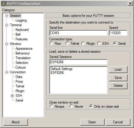
Click the Open button, and a PuTTY terminal session window should open.
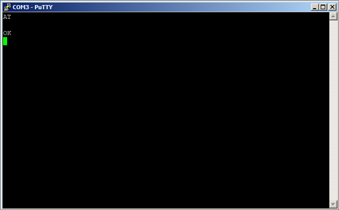
Enable Caps Lock on your PC, and type AT, but don’t press Enter. You should see AT in the PuTTY terminal window. If you don’t, you may have selected the wrong COM port or the wrong baud rate. Close PuTTY and start again at the top of this section. The permissible baud rates are: 9600, 19200, 38400, 74880, 115200, 230400, 460800, and 921600; try each one in turn until you find the one that works.
When you see AT in the PuTTY terminal window, while holding the Ctrl key down, press the M key followed by the J key. Release the Ctrl key. You should see OK in the PuTTY terminal window as shown in the picture below.
Note that if you make a typing mistake while in the terminal session window, it may not be possible to successfully correct the mistake. Rather than try to edit out your mistake, it is often better to simply hold down the Ctrl key, and press the M key followed by the J key, which will generate an Error message. Then, you can start again and type the correct input.
When you see that first OK message, you have cleared a big hurdle. Then you know that your hardware setup is correct, the ESP module is functional, you have selected the correct COM port, and you have chosen the correct baud rate. Close the PuTTY terminal session window, and click OK when PuTTY asks if you are sure.
Now, reopen PuTTY, select the ESP8266 saved session, and click the Load button. This should place your previously determined COM port and baud rate settings in the appropriate windows. Click the Open button, and a new PuTTY terminal session window will open.
Enable Caps Lock on your PC, and type AT, but don’t press Enter. You should see AT in the PuTTY terminal window. Type a + sign followed by GMR. When you see AT+GMR in the PuTTY terminal window, while holding the Ctrl key down, press the M key followed by the J key. Release the Ctrl key. You should see the ESP8266 firmware information in the PuTTY terminal window similar to that shown in the picture below.
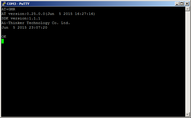
In the first line above, you see the AT+GMR command that you typed. As you may know or have guessed, the command scheme that you are using to communicate with the ESP8266 is called an “AT command set” because all the commands begin with the letters “AT.”
Unfortunately, there are many different versions of AT command sets; they all contain some of the same commands, but there are many AT commands that are not standard among all AT command sets. Even within the ESP8266 community, there are a number of versions. The second line above indicates that this particular 8266 device is programmed with firmware that uses version 0.25.0.0 of the AT commands. Somewhere there is a document that defines the commands that are included in version 0.25.0.0, but without that document you must use trial and error to determine the AT commands that work. That is a very tedious process at best, but fortunately there is a solution to the dilemma that will be explained shortly.
Line three identifies the Software Development Kit (SDK) version that was used for this particular ESP8266 as version 1.1.1. Each SDK also includes an AT command set that is part of the firmware, and that is suited for controlling that firmware. Ostensibly, AT version 0.25.0.0 works with SDK version 1.1.1. But still one needs the document that describes AT version 0.25.0.0 in order to know what commands are included. There is a better way as described in the next section of this article, but before you go there, try another AT command to see what happens.
Enable Caps Lock on your PC, and type AT+CWLAP. When you see AT+CWLAP in the PuTTY terminal window, while holding the Ctrl key down, press the M key followed by the J key. Release the Ctrl key. After a few seconds, the terminal window should look similar to the photo below.
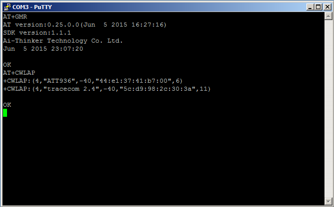
AT+CWLAP has commanded the ESP8266 to list all the Wi-Fi access points within its range. In the case above, two access points were found: one is called “ATT936” and the other is called “tracecom 2.4.” Your results will, of course, be different and should include your own Wi-Fi network plus those of any of your very close neighbors.
Close the PuTTY terminal session window, and click OK when PuTTY asks if you are sure.
ESP Flash Download Tool
Although it’s rarely mentioned on the Web, Espressif, the designers of the ESP8266 integrated circuit, have created a specific piece of software to update the firmware in their chips. It’s the ESP Flash Download Tool, and it’s available here. Download, extract, and install the latest version on your PC; as of this writing it’s FLASH_DOWNLOAD_TOOLS_v2.4_150924.rar.
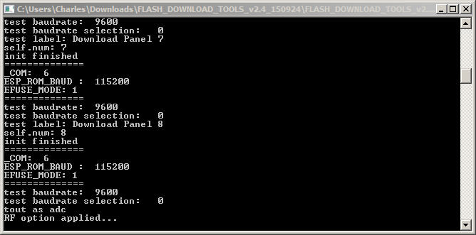
Start the tool, and you should see two windows open: a GUI window with places for you to enter information, and a terminal-like window that logs the actions taken.
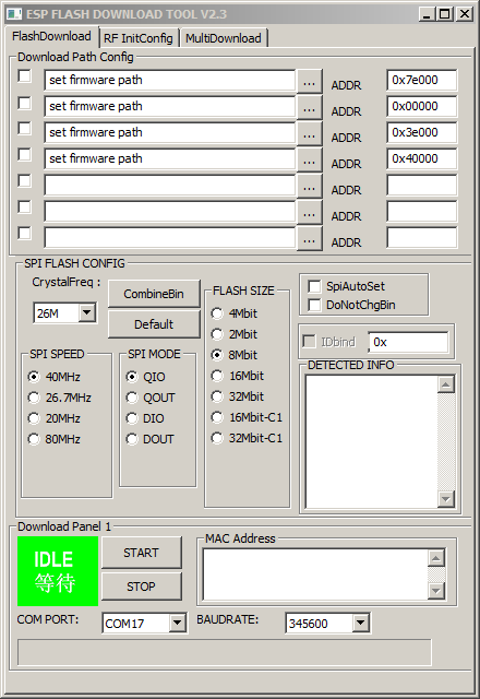
A few things are worth noting, but are not reasons for concern.
- The GUI window is identified as V2.3 while the log window is identified as V2.4. Apparently the GUI window is mislabeled.
- The GUI window COM port and baud rate may contain data.
- The GUI window address boxes may contain data.
- The log window may contain data.
Getting the Latest Firmware
Espressif has a page where they post the latest firmware available. Go to bbs.espressif.com, click on the SDKs entry under Downloads, and then click on “latest release” under Announcements. As of today, 28 Oct 2015, you will see a page that includes the following.
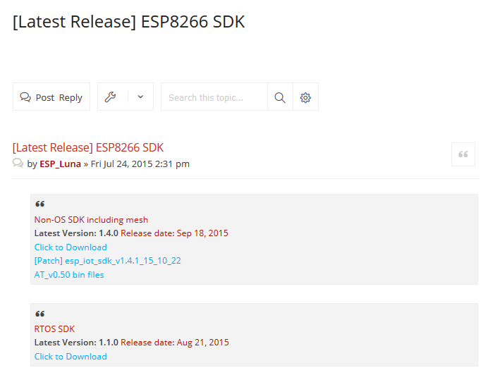
The latest release of the Non-OS SDK (Software Development Kit) is what you want, and it would seem that you could click just under “Latest Version: 1.4.0” and get the latest version. But that’s not quite right; notice that there is a patch available identified as esp_iot_sdk_v1.4.1_15_10_22. It’s not really a patch; it’s a corrected version of version 1.4.0, and was released on 22 Oct 2015. You want that and the AT_v0.50 bin files. Click on each of those in turn and download the files; you can save them wherever you want, but they are fine in the Downloads folder.
Of course, by the time you read this, there may be later SDK releases and their locations may be altered, but at least you know where to look. Just be sure that you read carefully to be sure you are getting the very latest version. As you have seen from the preceding, it’s not always obvious.
You may have noticed that there is a section for downloading documents. They all contain good information, but sometimes there is a substantial loss in the translation from Chinese to English. For now, be sure to get the latest versions of ESP8266 AT Instruction Set and Espressif IOT SDK User Manual; both are currently at version 1.4.
Installing the Firmware
Start the ESP flash download tool and make sure that none of the boxes at the top left of the GUI window are checked. Enter the COM port you are using, and a baud rate of 115200 in the boxes near the bottom of the window. Note that as you enter data, it is recorded in the log window.
Power up your ESP programming setup, and connect it to your PC. Press and hold the Reset button, and then press and hold the Flash button. Release the Reset button, and then release the Flash button. Click the START button in the flash download tool GUI window. The flash download tool should check the ESP8266 in your setup, and produce a report similar to the pictures shown below. Press and release the Reset button on you programming setup to exit the ESP8266 download mode and resume normal operation.
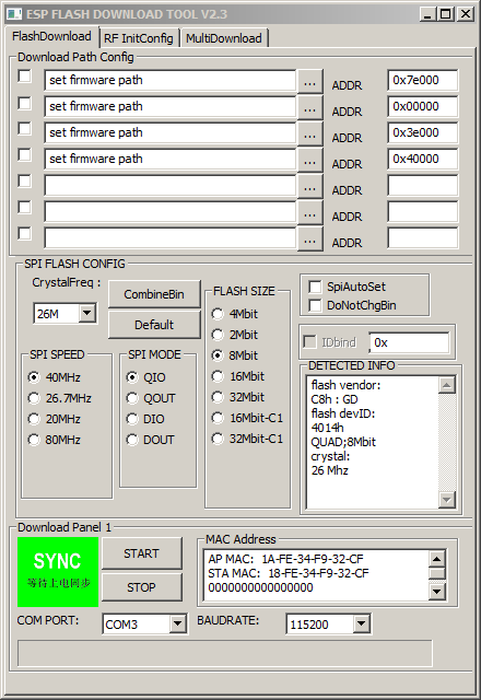
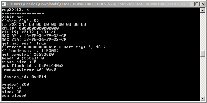
Notice that the GUI window now contains information about the ESP8266 including the size of the flash memory (8Mbit in the example,) the crystal frequency (26MHz in the example,) and two MAC addresses for the chip. The same information is contained in the log window.
Next, click the box in the GUI window labeled “SpiAutoSet,” which will cause the download tool to automatically select the correct flash size and crystal frequency.
Now, you need to select the files to be installed in the ESP8266 and set the starting memory address for each file. There are four files that must be correctly installed in order to update your ESP chip. Open the Espressif IOT SDK User Manual and find the section on writing images into flash. In version 1.4 of the manual, it begins on page 20. Next, locate the part that describes the version that supports Cloud Update (FOTA,) and within that part, find the table that pertains to the flash size in your ESP8266. In the example, the flash size is 8Mbits which is equal to 1024KB, so table 2 on page 25 of the manual provides the information needed for the example. See the picture below.
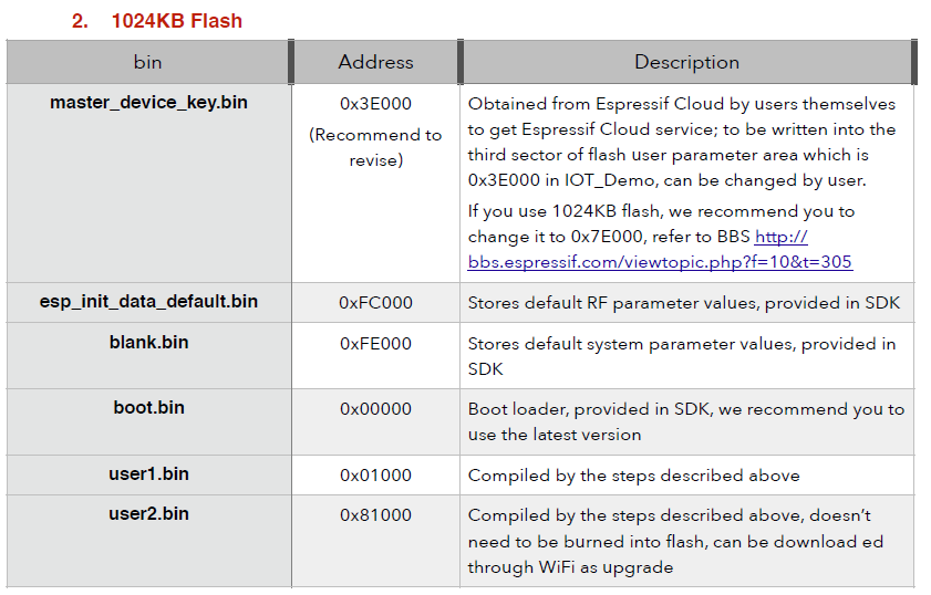
The four files needed are: esp_init_data_default.bin, blank.bin, boot.bin, and a user1.bin file. The address at which each file is to be installed is shown next to the file name. The first three of the required files are located in the esp_iot_sdk_v1.4.1_15_10_22 folder you previously downloaded from bbs.espressif.com, and the fourth is located in the AT_v0.50 bin files. Navigate to where those downloaded files are, and copy each one into one of the blanks at the top of the Flash Download Tool GUI window; enter the correct address for each file in the blank next to the file name. Follow these steps for each file.
- Click inside a file “set firmware path” space.
- Click the … button to the right of the space.
- Navigate to the location of the desired file and click the file. The GUI will automatically enter the file name in the space.
- Enter the correct address (from the table) for each file.
Note that the files to be flashed may not be exactly the same as those listed in the table, but will be a close variant. With a little examination and applied logic, the correct files should be readily apparent.
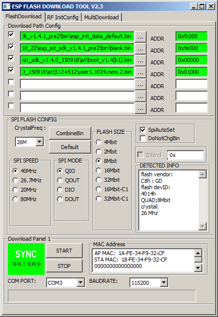
Now, click the four check boxes to the left of each file name. The Flash Download Tool GUI window should be similar to the picture below. Double check the addresses against the table.
On your ESP programming setup, press and hold the Reset button, and then press and hold the Flash button. Release the Reset button, and then release the Flash button. Click the START button in the Flash Download Tool GUI window. The download should begin, and its progress should be shown in the Flash Download Tool GUI window and the log window, as depicted below.
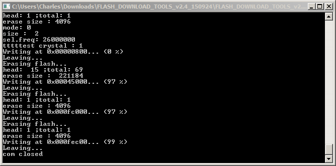
As shown above, a successful flash operation will result in all the files being sent to the ESP8266, and the COM port closed.
Checking for a Successful Flash
When the flash operation is complete, close the Flash Download Tool. Remove power from the ESP programming setup, and then reconnect the power.
Reopen PuTTY, select the ESP8266 saved session, and click the Load button. This should place your previously determined COM port and baud rate settings in the appropriate windows. Click the Open button, and a new PuTTY terminal session window will open.
Enable Caps Lock on your PC, and type AT, but don’t press Enter. You should see AT in the PuTTY terminal window. Type a + sign followed by GMR. When you see AT+GMR in the PuTTY terminal window, while holding the Ctrl key down, press the M key followed by the J key. Release the Ctrl key. You should see the ESP8266 firmware information in the PuTTY terminal window similar to that shown in the picture below.
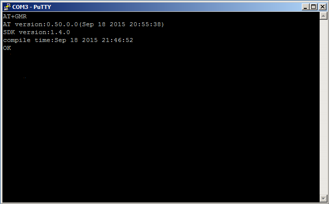
As you can see, new firmware is evident in the ESP8266. It has been updated from SDK version 1.1.1 to SDK version 1.4.0. In addition, the corresponding 0.50.0.0 version of the AT command set has also been installed, and is documented in ESP8266 AT Instruction Set, Version 1.4.
Close the PuTTY terminal session window, and click OK when PuTTY asks if you are sure.
Last Words
With a couple of practice sessions, the entire firmware flash process can be completed in much less time than it takes to read this article. Once it’s done, you can be confident of what is inside your 8266, and can focus on your Wi-Fi project instead of “guessing and hoping” about the ESP firmware and the necessary AT command set.
Dawon Kahng – Wikipedia
Dawon Kahng (May 4, 1931 – May 13, 1992) was a Korean-American electrical engineer known for his work at Solid-State Electronics.
Dawon was born on May 4, 1931 in Seoul, South Korea. He studied Physics at Seoul National University, Seoul, South Korea, and emigrated to the United States in 1955 to attendOhio State University, where he received a doctorate in physics.
He was a researcher at Bell Telephone Laboratories in Murray Hill, New Jersey and he invented MOSFET (Metal Oxide Semiconductor Field-Effect Transistor), which is the basic element in most of today’s electronic equipment, with Martin M Atalla in 1959. Along with his colleague Simon Sze, he also invented the floating gate memory cell, the foundation for many forms of semiconductor memory devices. He also conducted research on high frequency Schottky diodes, ferro-electric semiconductors, and luminous materials, and made important contributions to the field of electroluminescence. He also invented Floating Gate non-volatile semiconductor memory in 1967.
ESP8266 AT-Command firmware – ElectroDragon
Get Your ESP8266-12 Ready for AT Commands: 5 Steps (with Pictures)

Maker Corner: ESP8266 firmware update
Where do I add meta tags for my WordPress Site? – Frequently Asked Questions / WordPress – Swiftype Community Forums
Table of operators – Access
Source: Table of operators – Access