My first version of a stepper controller uses a 555 timer chip and a 74LS194 shift register. The tracking rate is controlled by the 555 timer chip through a resistor and a capacitor. By changing the resistance and capacitance values, the tracking rate also changes. A variable resistor is used to speed up and slow down the rotation of the stepper. Since the timing signals are controlled by analog components, the tracker suffers from issues related to the tracking rate. It usually requires ‘tracking rate adjustment’ (to match the movement of the sky) at the start of an imaging session. While it has served me for four years and used it to image some interesting targets, it is clear that an upgrade is needed.
Upon learning some basics about Arduino, I immediately saw the potential to use it as a controller for a stepper motor, the kind of motor used in devices that require precise motion control such as in many telescope mounts. I started looking at some excellent tutorials on the Internet and was able to build the simple stepper controller featured in this article.
The main advantage of using a microcontroller is that it makes it possible for the stepper controller to keep a far accurate tracking rate, unlike my previous controller that changes tracking rate with the slightest change in ambient temperature. Since it is digital, there is no need for a re-calibration at the start of every imaging session. Buttons can be placed to allow easy adjustment of the tracking speed such as to speed up or slow down the tracking rate momentarily, for easy adjustment. LEDs can be used as status indicators (e.g., current step rate).
After a few months, I have finally built a fairly simple yet reliable stepper controller that can be used to drive very small trackers, or even more advanced ones such as a telescope. And since it is built with an Arduino, it is possible to add some upgrades to it in the future.
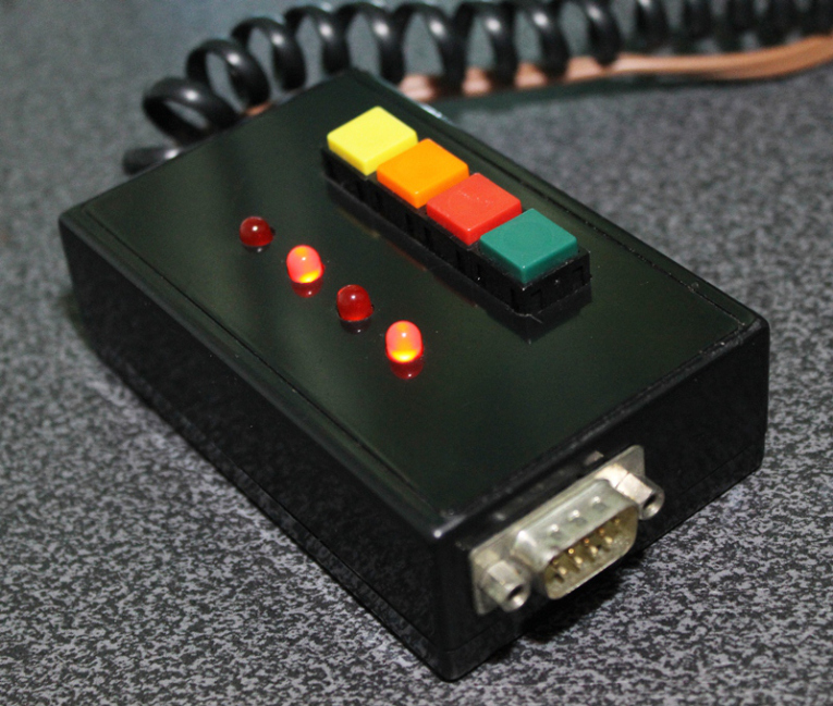
Controller for equatoral trackers such as a telescope mount with stepper motor
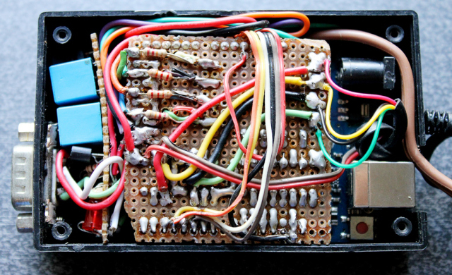
Removing the cover reveals the circuit board for the stepper driver. This circuit sits on top of the Arduino, much like a DIY shield (a circuit board that you can attach readily to an Arduino by stacking it on top of it, through the connecting pins.)
Stepper controller with the DIY stepper driver circuit.
Dismantled, you can clearly see the Arduino board on the left (there are many versions of an Arduino board, in this particular project, I have used what is called an Arduino UNO). You can see the connecting pins that run vertically on the board’s left and right sides. The pins connect the Arduino to the Stepper Driver (center). The Stepper Driver is a board that holds L293D chip and some PC817 optical isolators. Some LED lights were left on the board which could come handy during troubleshooting. Also visible is some sort of a relay circuit and its connector (right), to allow a GPUSB (some kind of a module that allows a computer to talk to my telescope mount) to control the DIY Stepper Controller for autoguiding purposes (it’s a completely optional feature that I decided to include as it may come handy in the future). The use of a GPUSB, however, will be discussed in a separate article.
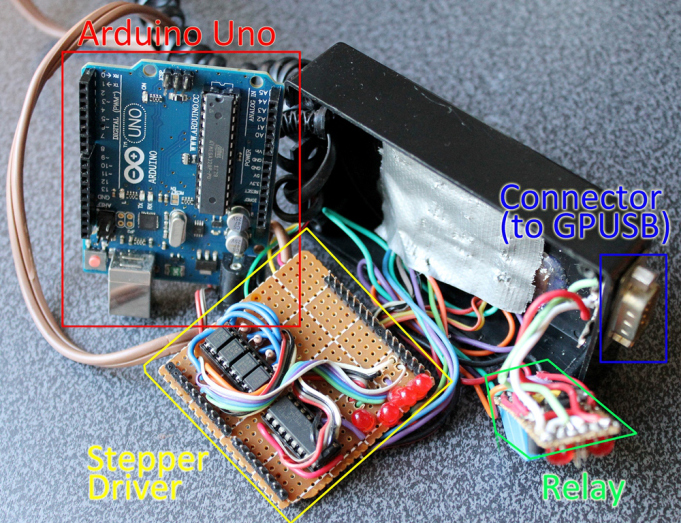
Components of the stepper controller. Only the Arduino Uno and the Stepper driver will be discussed in this article. The Relay and the Connector (for GPUSB) to enable a computer to send guiding signals to the stepper controller (for autoguiding purposes) will be discussed in a separate article.
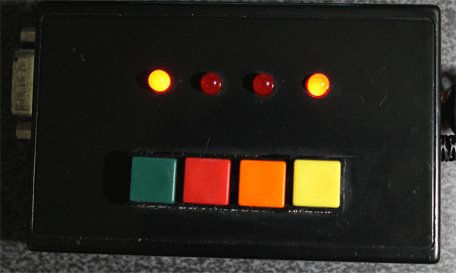
Here you can see the circuit board for the LED lights and the four push-button switches.
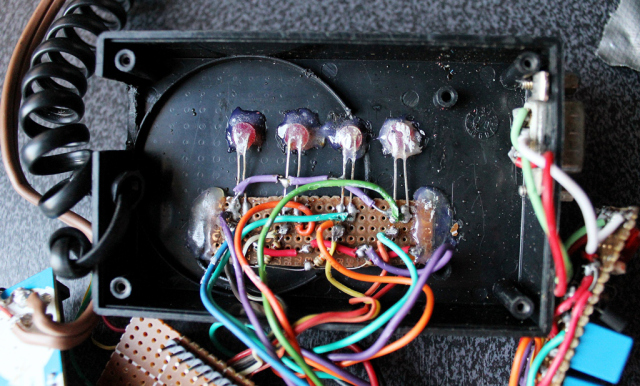
The circuit for the LED lights and the push-buttons.
To build this DIY Stepper Controller, you will be needing some basic understanding of electronic circuits. The diagram below illustrates how the parts will be put together.
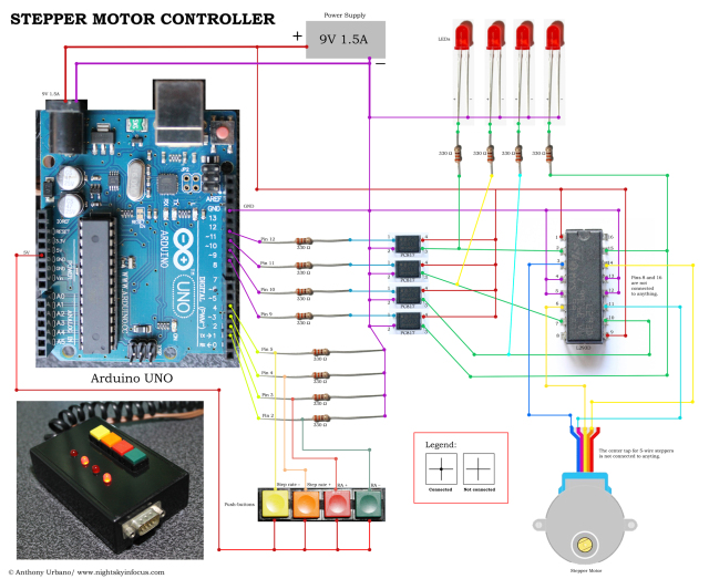
To view a larger image, click here. Circuit diagram for the Stepper Motor Controller. An Arduino Uno is used to provide pulses for the L293D H-bridge through optional PC817 opto-isolators. The circuit can drive both bipolar and unipolar steppers (operated in bipolar mode).
The Arduino board requires what is called a ‘sketch’. A screenshot of the sketch used in this DIY stepper controller is shown in the following photo. As you may have noticed, it is composed of lines of text with a set of instructions in it. It is a ‘program’ that you upload to the Arduino board to let it know what to do. This program is uploaded by connecting the Arduino board to a computer through a USB connection, using the Arduino Software. Learn more about Arduino. Once you are familiar with some basics, you will be able to understand how to use the sketch below.
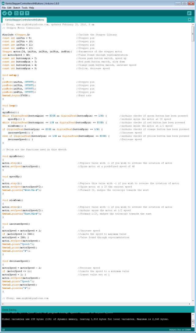
To view a larger image, click here. Script for the Arduino stepper motor controller. For inquiries about the sketch, please send an email to eteny@nightskyinfocus.com.
If the sketch above seems too complicated, you can try uploading a simpler sketch that can be used to spin the motor (note that this sketch does not read the buttons, it only spins the motor).
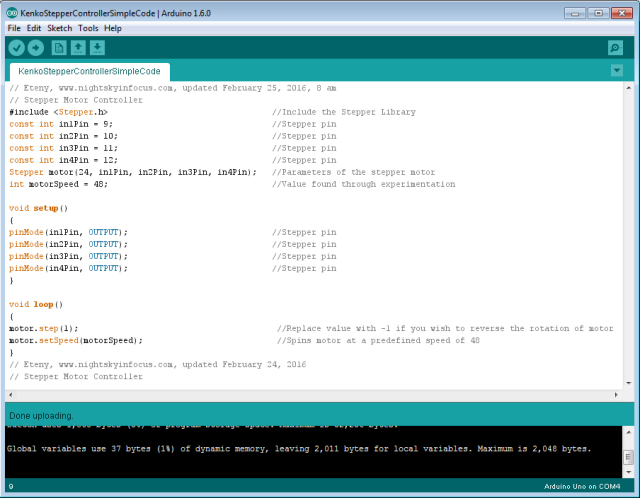
To view a larger image, click here. Script for the Arduino stepper motor controller. For inquiries about the sketch, please send an email to eteny@nightskyinfocus.com.
Once you’ve finished building the DIY Stepper Controller circuit above and uploaded the sketch to the Arduino board, you should see some blinking lights indicating that your controller is up and running and ready to track the skies!
Arduino stepper motor controller for a telescope mount.
This page is a work-in-progress. In future posts, I will describe an advanced application of the tracker such as enabling the Arduino stepper controller to receive commands from a computer through a serial connection, and perform automatic tracking error corrections (autoguiding) with a program running on a computer, such as PHD Guiding.
Visit this page for captured images and future upgrades on this project. Clear skies!

To view a larger image, click here. A 240-second test image to determine the tracker’s accuracy. The image was taken a focal length of 900 mm from a city with severe light pollution using a filter-modified Canon 450D DSLR. Tracking was guided using PHD2 Guiding software, a modified Logitech 4000 web camera, and a 400 mm focal length guide scope.
Related link:
Stepper Motor Controller (Analog)
Improvised Clock Drive Project
Source: DIY Stepper Controller using Arduino | Night Sky in Focus