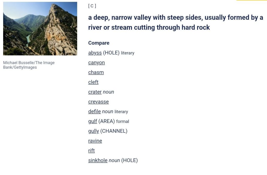
GORGE Dictionary Jovan Stosic September 20, 2024 https://dictionary.cambridge.org/dictionary/english/gorge
Input impedance vs frequency | Forum for Electronics Engineering and technology notes Jovan Stosic September 19, 2024 https://www.edaboard.com/threads/input-impedance-vs-frequency.232901/
Notes on Antenna Impedance Engineering and technology notes Jovan Stosic September 19, 2024 https://www.siranah.de/html/sail018r.htm
antenna – Understanding Impedance (R+jx) Engineering and technology notes Jovan Stosic September 19, 2024 https://ham.stackexchange.com/questions/20964/understanding-impedance-rjx
Siril Astronomy notes Photography and image processing videos Wishlist Jovan Stosic September 18, 2024 https://siril.org/
GraXpert Astronomy notes Photography and image processing videos Wishlist Jovan Stosic September 18, 2024 https://graxpert.com/
The Seventh Scroll (Ancient Egypt, #2) by Wilbur Smith Books read Jovan Stosic September 14, 2024 https://www.goodreads.com/book/show/416580.The_Seventh_Scroll
River God (Ancient Egypt, #1) by Wilbur Smith Books read Jovan Stosic September 14, 2024 https://www.goodreads.com/book/show/429138.River_God
A Gentleman in Moscow (TV Mini Series 2024) TV Series Seen Jovan Stosic September 8, 2024 https://www.imdb.com/title/tt8230448/