DALI commands

11.2   DALI commands

  • DALI commands are transmitted on the DALI bus at 1200 bit/sec using Manchester coding.
    In Manchester coding, the bit state is defined by a transition at the centre of the bit window (ie: NOT by the actual level)
    ie: positive going transition  = ‘1’, negative going transition = ‘0’.
    This needs a signal switching rate of twice the actual bit transmission rate.
  • DALI commands are transmitted as frames of 16 bits  (+ start and stop pulses)
  • Some commands have to be repeated to be effective (within 100mS)
    This is done automatically within the Rayzig DALI output module.
  • Some commands have 8 bit return frames.
    Raymon reports on the header panel: Return frame byte = nn
    OR if no response:  absent return frame.
  • Some commands have no return frame.
    Raymon reports: frame with no response.  

Addressing

DALI slave addressing is by one of:

  • Individual luminaires addressing using their short addresses (0–63)
  • Group addressing which accesses one of  16 groups (0-15)
    (Each luminaire can be assigned to one of more groups)
  • Broadcast which addresses all slave units on the DALI bus.

Scenes

Each luminaire can participate in one of more of 16 available DALI scenes.

For each scene, the luminaire stores a level (0-254) for that scene or 255 if not participating.

GOTO SCENE NN command causes each participating luminaire to switch to its level for scene NN.

Addressing in the 16 bit transmitted frame

A brief summary of DALI addressing is given in the table below.

The following coding is used to illustrate the bit usage:

S: selector bit:                        S = ‘0’ direct power level in lower byte

S = ‘1’ command in lower byte

Y: short or group address:        Y = ‘0’ short address

Y = ‘1’ group address or broadcast

A: significant address bit

C: significant command bit


 Type of addressing

address byte

Short addresses (0-63)

0AAAAAAS

Group addresses (0-15)

100AAAAS

Broadcast

1111111S

Special command

101CCCC1

Special command

110CCCC1

The table below lists the DALI commands currently used by Rayzig.

List of  DALI commands used by Rayzig (part 1)

Operational control in Rayzig uses only DIRECT POWER CONTROL and OFF with individual and group addressing

plus GOTO SCENE with broadcast addressing.

The other commands are used in configuration.  (Greyed-out commands are unused)

DALI commands was last modified: September 14th, 2021 by Jovan Stosic

DALI commands tab

11.17   DALI module configuration – command tab

The DALI configuration window opens on the Luminaire list tab page.  

Click the Commands tab at the top to switch to the commands tab page.

The commands tab page is in several sections as shown below.

Each is section is discussed separately.

 Double click for full sized image

Level setting

There are three level/value setting spin-edit controls on the page.

A slider control allows rapid setting of these three controls.

Note that these level controls are DALI levels (0-254). The % value corresponds to Rayzig levels (0-100).


The  sends the specified level to luminaires, according to the current

addressing setting (ie: one luminaire or a luminaire group or a broadcast to all luminaires).

Address, scene and group controls

These controls all have drop down lists which allow rapid value setting by selection.

Command information

The following data is displayed for some commands.   See: DALI commands – DALI addressing

The last transmitted 16 bit frame

The address byte

General commands and addressing

There are eight buttons as shown below.

These can act on luminaires addressed  as luminaires or groups or by broadcast to all luminaires.

In the example below, luminaire addressing is selected for luminaire 2.

Note that operational control by Rayzig only uses the Off command for an OFF action.

Rayzig ON and level changes actions use direct power level setting.

The addressing settings are used by the eight buttons, by Goto scene and for Direct power level setting.

Setting luminaire control values

This panel allows the setting of six luminaire control parameters as shown on the buttons.

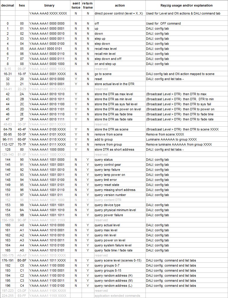
The setting process of each button makes use of two DALI commands:

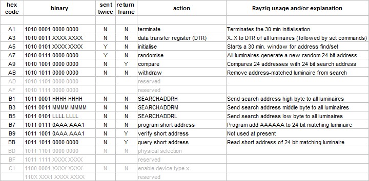
  • Extended command A3 (DATA TRANSFER REGISTER)  is broadcast to put
    the new value into the Data Transfer Register (DTR) of all luminaires.
  • A button-specific command, eg:  42 ( STORE DTR AS MAX LEVEL) is then sent to luminaire 2
    to make it use its newly set DTR value as a new maximum level.

The button: Send value to all DTRs sends extended command A3,

 ie: just the first of the two commands above.

Note than some luminaire parameters (eg: minimum level) may have fixed internal lower limits.

Reading luminaire values

These 18 buttons use the same luminaire address box as the setting buttons.

They send a single command, eg:  161 = QUERY_MAX_LEVEL

Note that Query fade time/rate is a single DALI command which returns an 8 bit byte.

The lower 4 bits are fade rate and the upper 4 bits are fade time.

DALI group management

This panel duplicates the functions of the group editor window accessed from the luminaire listing.

Current group membership is displayed automatically on changing the luminaire selection.

If a luminaire list has been built on the listing tab page, then group membership information

is immediately available. If not, then it is read from the selected luminaire.

Changes to group membership automatically update the group membership sub-panel.

The luminaire list is automatically updated with the revised group membership on returning
to the listing tab page.


DALI scene management

This panel duplicates the functions of the scene editor window accessed from the luminaire listing.

Current scene membership and levels are displayed automatically on changing the luminaire selection.

If a luminaire list has been built on the listing tab page, and scene data added, then scene information

is immediately available. If not, then Raymon reads the 16 scene levels of the selected luminaire.

Changes to scene settings update the scene membership sub-panel and scene level display.

The luminaire list is automatically updated with the revised scene information on returning
to the listing tab page.


Manual commissioning – binary searches and address assignment

The controls for address assignment duplicate the functions of the same controls

on the listing tab page. The detailed description is therefore not repeated here.

Please see:        DALI addressing new luminaires  DALI new + existing luminaires

               DALI address setting explained

The Send 24 bit search address and compare button performs one cycle of the binary search process.

It allows you to perform a binary search by manually changing the 24 bit search address after each cycle.

The Luminaires sub-panel has the following buttons:

  • Reset Luminaire which clears all data except the short address.
  • Query 24 bit address which reads the 24 bit random address of a specified luminaire.
  • Query luminaire address using 24 bit address. This button returns the short address
    of a luminaire that has been found by a binary search.
    ie: The luminaire with random address = the search address currently in its search buffer
    (This is the search address broadcast by the most recent Search and Compare action.
    Such action is performed by the Search and compare button or each stage of a binary search.)
  • The Use invalid switch is explained in:  DALI search – Use invalid


DALI commands tab was last modified: September 14th, 2021 by Jovan Stosic

Have you tried NB-IoT? | QUECTEL

AT+NBAND=20 //Set APN for PDP context, (“”) from operator

AT+CGDCONT=1,”IP”,”u.iot.mt.gr.hu” //Enable network registration, connection & PSM URCs

AT+CEREG=2

AT+CSCON=1

AT+NPSMR=1

Manual operator selection:

1. Turn on the modem:
AT+CFUN=1 // set MCC MNC values, ex: 123456 pre MCC=123 MNC=56

2. Log in ( 30 seconds ):

AT+COPS=1,2,”21630″

3. Registration:

/ wait 30 sec for NW registration of URC 1=home alebo 5=roaming /

+CEREG:1,xxxx,yyyyy,z

+CEREG:5,xxxx,yyyyy,z

Send/Receive UDP data:

1. create an UDP socket
AT+NSOCR= DGRAM,17,16666,1

0

2. send UDP message
AT+NSOST=0,83.58.228.64,16666,12,48656C6C6F20576F726C6421

0,12

+NSONMI:0,12

3. received UDP message

AT+NSORF=0,12

0,83.58.228.64,16666,12,48656C6C6F20576F726C6421,0

4. close socket

AT+NSOCL=0

https://www.soselectronic.com/articles/quectel/have-you-tried-nb-iot-2178

Have you tried NB-IoT? | QUECTEL was last modified: September 8th, 2021 by Jovan Stosic

DSLR focus control with gphoto2

DSLR focus control with gphoto2

If you read the documentation on gphoto2 regarding the focus control (“manual” focus as they call it) it mentions that focus control only works while liveview mode is on, and that seemed to be sufficient for Canon, but it turned out that for Nikon cameras there was more to it than just liveview.

First the necessary disclaimer though: I’ve only tried the Nikon D5100 here and Canon 550D and 600D, so YMMV.

But let’s start with liveview (or preview) mode itself first – this one is controlled by “/main/actions/viewfinder” setting in both Nikon and Canon.

Essentially it’s name is “viewfinder mode”. That’s how it’s actually called by GPhotow – when you get list of camera properties via GPhoto2 on Canon it’s name is “Canon EOS Viewfinder”, and on Nikon “Nikon Viewfinder” (key is same – “/main/actions/viewfinder” – on both). So let’s not call it liveview/preview mode anymore – it’s viewfinder mode hereafter.

Next thing to be aware of is that this mode is switched off when gphoto2 releases the camera. So running command-line tool “gphoto2” with parameters “–set-config /main/actions/viewfinder=1” is not the right way to do it – gphoto2 will enable viewfinder mode, then since no more commands are there it’s going to quit, and on quit it will release the camera, which will disable viewfinder mode.

So just run gphoto2 in interactive mode (if you use gphoto2 in command line – if you use gphoto2 library and call it’s API methods you’re fine, just be aware that doing camera release – actually the method name is gp_camera_exit – will disable viewfinder mode).

Also the viewfinder mode will disable itself after some seconds of camera inactivity (you’ll hear the clicking when it does that). Maybe this is configurable somewhere in the menus, but I didn’t find out where, and in general one should just be aware of it behaving that way by default.

Ok, so we run “gphoto2 –shell” to start gphoto2 command-line tool in interactive mode, do “set-config /main/actions/viewfinder=1”, what’s next?

Well, one more sanity check thing to do is to make sure on your lens the physical switch from auto to manual focus is set to auto – that enables your DSLR body to control the focus, but doesn’t necessarily means autofocusing. Which might be confusing for some.

Then on Canon I could just set “/main/actions/manualfocusdrive” to one of those “Near 1/2/3 or Far 1/2/3” values and that got focus engine rotate the lens accordingly. But not on Nikon.

Experimentally I’ve found out that on Nikon I also have to set these (works for me in this specific order):

  • /main/actions/viewfinder=1 (enable viewfinder mode first, as you already know)
  • /main/capturesettings/focusmode2=MF (selection) – don’t bother with
  • /main/capturesettings/liveviewaffocus=Single-servo AF
  • Then control focusing engine via /main/actions/manualfocusdrive (set to 1000/-1000 to see clear rotation)

Again, this is what I had found out on Nikon D5100 specifically, but I assume it’s more/less same for all or most Nikon DSLRs.

That’s it. Now go and programmatically control that focus on your Nikon 🙂

Source: DSLR focus control with gphoto2 | M.V.M-n.

DSLR focus control with gphoto2 was last modified: September 6th, 2021 by Jovan Stosic