Month: March 2017
160mm vs. 180mm rotor Pro/Cons?- Mtbr.com
nd here.
Suspicion (1941)
Directed by Alfred Hitchcock. With Cary Grant, Joan Fontaine, Cedric Hardwicke, Nigel Bruce. A shy young heiress marries a charming gentleman, and soon begins to suspect he is planning to murder her.
Source: Suspicion (1941) – IMDb
Otkriven misteriozan objekt u našem Sunčevom sustavu – Dnevnik.hr
Understanding Metering and Metering Modes
Understanding Metering and Metering Modes
Every modern DSLR has something called “Metering Mode”, also known as “Camera Metering”, “Exposure Metering” or simply “Metering”. Knowing how metering works and what each of the metering modes does is important in photography, because it helps photographers control their exposure with minimum effort and take better pictures in unusual lighting situations. In this understanding metering modes article, I will explain what metering is, how it works and how you can use it for your digital photography.
When I got my first DSLR (Nikon D80), one of my frustrations was that some images would come out too bright or too dark. I had no idea how to fix it, until one day, when I learned about camera metering modes.
1) What is Metering?
Metering is how your camera determines what the correct shutter speed and aperture should be, depending on the amount of light that goes into the camera and the sensitivity of the sensor. Back in the old days of photography, cameras were not equipped with a light “meter”, which is a sensor that measures the amount and intensity of light. Photographers had to use hand-held light meters to determine the optimal exposure. Obviously, because the work was shot on film, they could not preview or see the results immediately, which is why they religiously relied on those light meters.
Today, every DSLR has an integrated light meter that automatically measures the reflected light and determines the optimal exposure. The most common metering modes in digital cameras today are:
- Matrix Metering (Nikon), also known as Evaluative Metering (Canon)
- Center-weighted Metering
- Spot Metering
Some Canon EOS models also offer “Partial Metering”, which is similar to Spot Metering, except the covered area is larger (approximately 8% of the viewfinder area near the center vs 3.5% in Spot Metering).
You can see the camera meter in action when you shoot in Manual Mode – look inside the viewfinder and you will see bars going left or right, with a zero in the middle, as illustrated below.
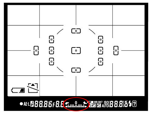
If you point your camera at a very bright area, the bars will go to “+” side, indicating that there is too much light for the current exposure settings. If you point your camera at a very dark area, the bars will go to the “-” side, indicating that there is not enough light. You would then need to increase or decrease your shutter speed to get to “0”, which is the optimal exposure, according to your camera meter.
A camera meter is not only useful for just the Manual Mode – when you choose another mode such as Aperture Priority, Shutter Priority or Program Mode, the camera automatically adjusts the settings based on what it reads from the meter.
1.1) Problems with Metering
Camera meters work great when the scene is lit evenly. However, it gets problematic and challenging for light meters to determine the exposure, when there are objects with different light levels and intensities. For example, if you are taking a picture of the blue sky with no clouds or sun in the frame, the image will be correctly exposed, because there is just one light level to deal with. The job gets a little harder if you add a few clouds into the image – the meter now needs to evaluate the brightness of the clouds versus the brightness of the sky and try to determine the optimal exposure. As a result, the camera meter might brighten up the sky a little bit in order to properly expose the white clouds – otherwise, the clouds would look too white or “overexposed”.
What would happen if you added a big mountain into the scene? Now the camera meter would see that there is a large object that is much darker (relative to the clouds and the sky), and it would try to come up with something in the middle, so that the mountain is properly exposed as well. By default, the camera meter looks at the light levels in the entire frame and tries to come up with an exposure that balances the bright and the dark areas of the image.
2) Matrix / Evaluative Metering
Matrix Metering or Evaluative Metering mode is the default metering mode on most DSLRs. It works similarly to the above example by dividing the entire frame into multiple “zones”, which are then all analyzed on individual basis for light and dark tones. One of the key factors (in addition to color, distance, subjects, highlights, etc) that affects matrix metering, is where the camera focus point is set to. After reading information from all individual zones, the metering system looks at where you focused within the frame and marks it more important than all other zones. There are many other variables used in the equation, which differ from manufacturer to manufacturer. Nikon, for example, also compares image data to a database of thousands of pictures for exposure calculation.

You should use this mode for most of your photography, since it will generally do a pretty good job in determining the correct exposure. I leave my camera metering mode on matrix metering for most of my photography needs, including landscape and portrait photography.
3) Center-weighted Metering
Using the whole frame for determining the correct exposure is not always desirable. What if you are trying to take a headshot of a person with the sun behind? This is where center-weighted metering comes in handy. Center-weighted Metering evaluates the light in the middle of the frame and its surroundings and ignores the corners. Compared to Matrix Metering, Center-weighted Metering does not look at the focus point you select and only evaluates the middle area of the image.

Use this mode when you want the camera to prioritize the middle of the frame, which works great for close-up portraits and relatively large subjects that are in the middle of the frame. For example, if you were taking a headshot of a person with the sun behind him/her, then this mode would expose the face of the person correctly, even though everything else would probably get heavily overexposed.
4) Spot Metering
Spot Metering only evaluates the light around your focus point and ignores everything else. It evaluates a single zone/cell and calculates exposure based on that single area, nothing else. I personally use this mode a lot for my bird photography, because the birds mostly occupy a small area of the frame and I need to make sure that I expose them properly, whether the background is bright or dark. Because the light is evaluated where I place my focus point, I could get an accurate exposure on the bird even when the bird is in the corner of the frame. Also, if you were taking a picture of a person with the sun behind but they occupied a small part of the frame, it is best to use the spot metering mode instead. When your subjects do not take much of the space, using Matrix or Center-weighted metering modes would most likely result in a silhouette, if the subject was back-lit. Spot metering works great for back-lit subjects like that.

Another good example of using spot metering is when photographing the Moon. Because the moon would take up a small portion of the frame and the sky is completely dark around it, it is best to use Spot metering – that way, we are only looking at the light level coming from the moon and nothing else.
Some DSLRs like the Canon 1D/1Ds are capable of multi-spot metering, which basically allows choosing multiple spots to measure light and come up with an average value for a good exposure.
5) How to Change Camera Metering Mode
Unfortunately, this varies not only from manufacturer to manufacturer, but also from model to model. On the Nikon D5500, for example, it is done through the menu setting (Info button). On professional cameras such as the Nikon D810 and Nikon D5, there is a separate button on the top left dial for camera metering. Changing metering on Canon cameras also varies from model to model, but generally it is done through a key combination (“Set” button), camera menu or a dedicated metering button close to the top LCD.
Source: https://photographylife.com/understanding-metering-modes
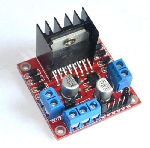
Control DC and Stepper Motors With L298N Dual Motor Controller Modules and Arduino
You don’t have to spend a lot of money to control motors with an Arduino or compatible board. After some hunting around we found a neat motor control module based on the L298N H-bridge IC that can allows you to control the speed and direction of two DC motors, or control one bipolar stepper motor with ease.The L298N H-bridge module can be used with motors that have a voltage of between 5 and 35V DC. With the module used in this tutorial, there is also an onboard 5V regulator, so if your supply voltage is up to 12V you can also source 5V from the board. So let’s get started!
Source: Control DC and Stepper Motors With L298N Dual Motor Controller Modules and Arduino
Wiznet W5100 (Ethernet Shield) Buffer Question.
So it looks like there is 8Kb of internal RX buffer on the W5100 chip… so how does one deal with reading the data faster than its coming in? If I don’t read it fast enough or too fast what happens? How do you flush the buffer on chip via client.flush()? I suspect it’s FIFO. I’m running into a situation where I am getting 8k of data posted to me and it looks like the data is being “clipped” … guess the buffer is getting filled.Looking at the W5100.c file there is mention of how the memory channels are allocated… anyone know how it’s setup to work? Full 8kb or less?
Arduino Modules – L298N Dual H-Bridge Motor Controller
Quick and simple start guide for using and exploring an L298N Dual H-Bridge Motor Controller module with an Arduino.The model in the example I am using is from Ebay. Materials needed: L298N Dual H-Bridge Motor Controller module (various models will work) Male to Female jumper wires An Arduino, any flavor. A DC power supply, 7-35vA motor that is the correct voltage for your power supply used.
Source: Arduino Modules – L298N Dual H-Bridge Motor Controller
DIY Stepper Controller using Arduino | Night Sky in Focus
My first version of a stepper controller uses a 555 timer chip and a 74LS194 shift register. The tracking rate is controlled by the 555 timer chip through a resistor and a capacitor. By changing the resistance and capacitance values, the tracking rate also changes. A variable resistor is used to speed up and slow down the rotation of the stepper. Since the timing signals are controlled by analog components, the tracker suffers from issues related to the tracking rate. It usually requires ‘tracking rate adjustment’ (to match the movement of the sky) at the start of an imaging session. While it has served me for four years and used it to image some interesting targets, it is clear that an upgrade is needed.
Upon learning some basics about Arduino, I immediately saw the potential to use it as a controller for a stepper motor, the kind of motor used in devices that require precise motion control such as in many telescope mounts. I started looking at some excellent tutorials on the Internet and was able to build the simple stepper controller featured in this article.
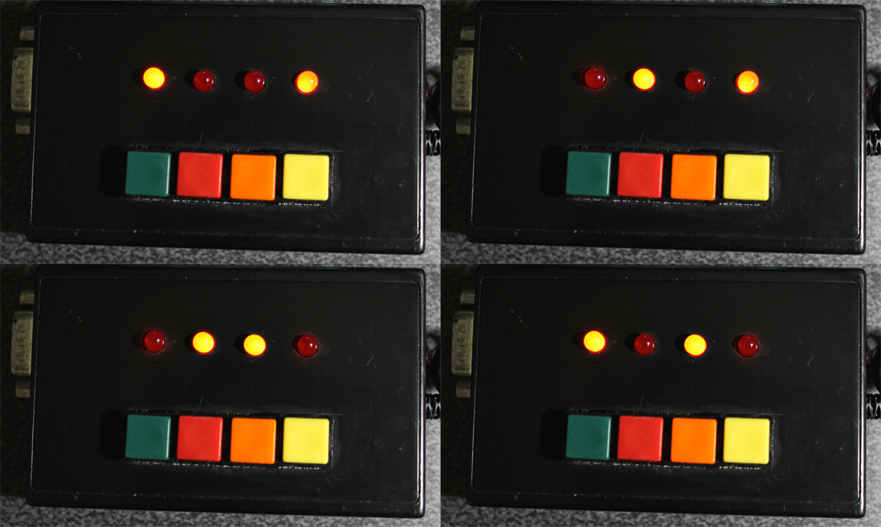
The main advantage of using a microcontroller is that it makes it possible for the stepper controller to keep a far accurate tracking rate, unlike my previous controller that changes tracking rate with the slightest change in ambient temperature. Since it is digital, there is no need for a re-calibration at the start of every imaging session. Buttons can be placed to allow easy adjustment of the tracking speed such as to speed up or slow down the tracking rate momentarily, for easy adjustment. LEDs can be used as status indicators (e.g., current step rate).
After a few months, I have finally built a fairly simple yet reliable stepper controller that can be used to drive very small trackers, or even more advanced ones such as a telescope. And since it is built with an Arduino, it is possible to add some upgrades to it in the future.
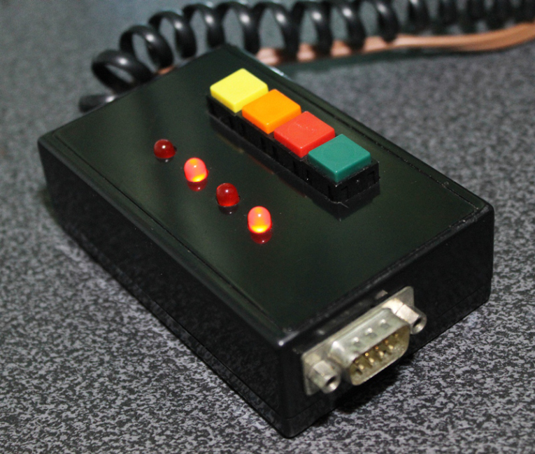
Controller for equatoral trackers such as a telescope mount with stepper motor
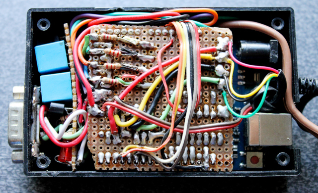
Removing the cover reveals the circuit board for the stepper driver. This circuit sits on top of the Arduino, much like a DIY shield (a circuit board that you can attach readily to an Arduino by stacking it on top of it, through the connecting pins.)
Dismantled, you can clearly see the Arduino board on the left (there are many versions of an Arduino board, in this particular project, I have used what is called an Arduino UNO). You can see the connecting pins that run vertically on the board’s left and right sides. The pins connect the Arduino to the Stepper Driver (center). The Stepper Driver is a board that holds L293D chip and some PC817 optical isolators. Some LED lights were left on the board which could come handy during troubleshooting. Also visible is some sort of a relay circuit and its connector (right), to allow a GPUSB (some kind of a module that allows a computer to talk to my telescope mount) to control the DIY Stepper Controller for autoguiding purposes (it’s a completely optional feature that I decided to include as it may come handy in the future). The use of a GPUSB, however, will be discussed in a separate article.
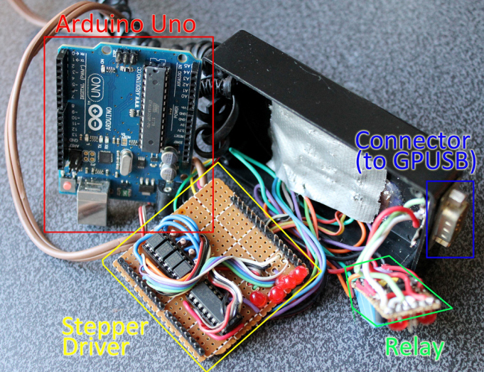
Components of the stepper controller. Only the Arduino Uno and the Stepper driver will be discussed in this article. The Relay and the Connector (for GPUSB) to enable a computer to send guiding signals to the stepper controller (for autoguiding purposes) will be discussed in a separate article.
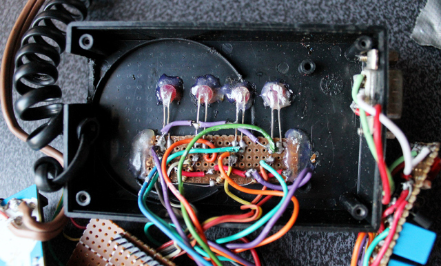
Here you can see the circuit board for the LED lights and the four push-button switches.
To build this DIY Stepper Controller, you will be needing some basic understanding of electronic circuits. The diagram below illustrates how the parts will be put together.
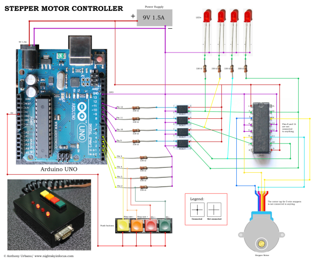
To view a larger image, click here. Circuit diagram for the Stepper Motor Controller. An Arduino Uno is used to provide pulses for the L293D H-bridge through optional PC817 opto-isolators. The circuit can drive both bipolar and unipolar steppers (operated in bipolar mode).
The Arduino board requires what is called a ‘sketch’. A screenshot of the sketch used in this DIY stepper controller is shown in the following photo. As you may have noticed, it is composed of lines of text with a set of instructions in it. It is a ‘program’ that you upload to the Arduino board to let it know what to do. This program is uploaded by connecting the Arduino board to a computer through a USB connection, using the Arduino Software. Learn more about Arduino. Once you are familiar with some basics, you will be able to understand how to use the sketch below.
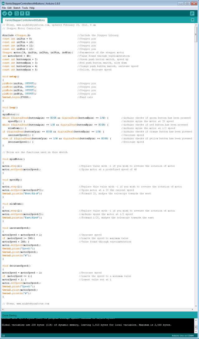
To view a larger image, click here. Script for the Arduino stepper motor controller. For inquiries about the sketch, please send an email to eteny@nightskyinfocus.com.
If the sketch above seems too complicated, you can try uploading a simpler sketch that can be used to spin the motor (note that this sketch does not read the buttons, it only spins the motor).
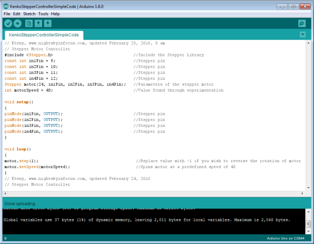
To view a larger image, click here. Script for the Arduino stepper motor controller. For inquiries about the sketch, please send an email to eteny@nightskyinfocus.com.
Once you’ve finished building the DIY Stepper Controller circuit above and uploaded the sketch to the Arduino board, you should see some blinking lights indicating that your controller is up and running and ready to track the skies!
This page is a work-in-progress. In future posts, I will describe an advanced application of the tracker such as enabling the Arduino stepper controller to receive commands from a computer through a serial connection, and perform automatic tracking error corrections (autoguiding) with a program running on a computer, such as PHD Guiding.
Visit this page for captured images and future upgrades on this project. Clear skies!
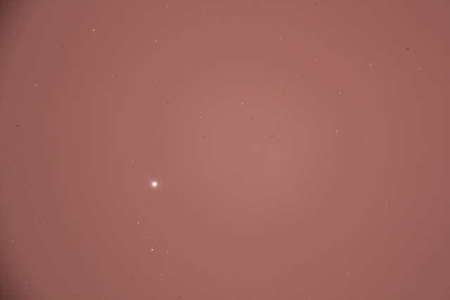
To view a larger image, click here. A 240-second test image to determine the tracker’s accuracy. The image was taken a focal length of 900 mm from a city with severe light pollution using a filter-modified Canon 450D DSLR. Tracking was guided using PHD2 Guiding software, a modified Logitech 4000 web camera, and a 400 mm focal length guide scope.
Related link:
Stepper Motor Controller (Analog)
Improvised Clock Drive Project
Source: DIY Stepper Controller using Arduino | Night Sky in Focus
Arduino Tutorial Series | JeremyBlum.com
Bringing Electrical Engineering to the Masses Following my 2010 Ignite Ithaca Talk, I was approached by element14 electronics; they were looking to contract enthusiastic engineers to generate an al…
