Engineering and technology

ESP8266-01 Pin Magic How to use the ESP8266-01 pins

Introduction

ESP8266-01 is a very low cost WiFi enabled chip. But it has very limited I/O. At first glance, once you configure it for programming all the pins are used. This page builds on Using ESP8266 GPIO0/GPIO2/GPIO15 pins to show you how you can get four (4) usable inputs/outputs for you next ESP8266-01 project and how to use IC2 to get even more inputs.

The code here assumes you are programming the module using the Arduino IDE setup as described on https://github.com/esp8266/arduino under Installing With Boards Manager. When opening the Boards Manager from the Tools → Board menu and select Type Contributed and install the esp8266 platform. Also see ESP8266 Programming Tips (espcomm failed)

ESP8266-01 Pins

The ESP8266-01 is the smallest ESP8266 module and only has 8 pins. Of these VCC, GND, RST (reset) and CH_PD (chip select) are not I/O pins but are needed the operation of the module. This leaves GPIO0, GPIO2, TX and RX available as possible I/O pins, but even these have pre-assigned functions. The GPIO0 and GPIO2 determine what mode the module starts up in and the TX/RX pins are used to program the module and for Serial I/O, commonly used for debugging. GPIO0 and GPIO2 need to have pull-up resistors connected to ensure the module starts up correctly.

Best Trick – Use I2C

The best trick to get extra inputs into the ESP8266-01 is to use an I2C interface.

One choice is to use GPIO0 and GPIO2 as the I2C bus.

The pullup resistors needed to get the module to start up correctly can double as the I2C bus pull-up resistors and the other, slave, components on the bus are open collector and so should not pull the bus down on power-up. However in some cases slaves, particularly those with battery backup, can become stuck and hold the bus down. In those cases you will need to isolate the bus until the ESP8266 gets through its boot stage.

You can avoid this issue by using TX and RX for the I2C bus
A few things to note:

  1. GPIO1 (TX) is used as the Data line, because you will always get some debug output on GPIO1 on power up. There is no way to suppress this output, but the Clock line (RX) will be held high so none of this data will be clocked to the slaves
  2. When programming the ESP8266, the RX line is connected to the programmer’s output. At the end of the programming the ESP8266 reboots and 330 Protection resistor prevents RX shorting the programmer’s output drive.
  3. The I2C series resistors provide similar protection for the TX, RX from shorts on the I2C bus

The ESP8266 is 3.3V device so preferably use 3.3V I2C slaves. Many, but not all, I2C devices are are 3.3V these days. “In general, in a system where one device is at a higher voltage than another, it may be possible to connect the two devices via I2C without any level shifting circuitry in between them. The trick is to connect the pull-up resistors to the lower of the two voltages.” (SparkFun I2C tutorial) For a mixture of 5V and 3.3V devices connect the pullup resistors to the 3.3V line, as shown above.

Using I2C is a great way to add a multi-channel A-to-D converter to the ESP8266-01 which does not expose the single ADC input of the underlying module. For example using Adafruit 12bit I2C 4 channel ADC or for analog output SparkFun’s I2C DAC Breakout – MCP4725 board. Many other types of sensors are also available with I2C buses.

See http://www.i2c-bus.org/i2c-primer/common-problems/ for more information of overcoming I2C problems. Also see Reliable Startup for I2C Battery Backed RTC for a short method to help clear the bus

Using the GPIO0 /GPIO2 for OUTPUT and RX for INPUT

While can send debug messages over the WiFi connection it is often convenient to use the TX connection. The next example show how to use GPIO0 and GPIO2 as outputs and RX as an input.


Using
Serial.begin(115200,SERIAL_8N1,SERIAL_TX_ONLY);
allows you to use RX as a general purpose input (or another output), while still writing debug messages to Serial. Again the 330 ohm resistor in the RX lead to the Flash programmer protects against shorting out the programmer’s driver.

NOTE: S1 will have to be open in order to program the ESP8266.

The TX pin accessed from the sketch as GPIO1 and RX is GPIO3

Another Trick – Driving a Relay and Reading a Push Button using GPIO0 / GPIO2

Here is another way of configuring the pins. Note: This trick only works if you have a relay module with an isolated input (N1 and N1-com). Because of this limitation and the complexity of the supporting code, the previous example, using RX as an input, is preferable.

Using ESP8266 GPIO0/GPIO2/GPIO15 pins has already covered how to use GPIO0/GPIO2 together to get an extra input. Here that example will be extended to use GPIO0 as an relay driver output and GPIO0/GPIO2 as an input without using RX or TX.

Here is the schematic as a pdf.

Here GPIO0 is used as an output to drive the relay and GPIO0/GPIO2 is used as an input to read the momentary push button which is used as a manual override to turn the relay on and off, in addition to the remote control over the WiFi connection. The momentary push button is also used to enable the config mode if it is press when power is applied.

The trick here is to do all this while still keeping GPIO0 and GPIO2 high when the ESP8266 module is initializing.

The pull-up resistors, R1 and R3, provide the necessary High for these two pins, but you have to ensure that any extra circuitry attached to GPIO0 and GPIO2 cannot not pull pins low. The optically isolated relay is connected between +3.3V and GPIO0. This keeps GPIO0 high on start up but allows GPIO0 to be made an output, after startup, and ground the relay input to operate the relay. It does not matter if the momentary push button is operated while the module is initializing, as that just connects GPIO0 to GPIO2 and connect both of these to their pullup resistors.

Detecting Config Mode

Using the ESP8266 as a temporary access point you can configure it via a web page as described here. Part of that process is to use a push button, or shorting link, on power-up to indicate to the software that you want to enter config mode.

Once the ESP8266 module has initialized, it runs the setup() code. In that code, to detect if the momentary push button is pressed, you need not make GPIO0 low to supply a GND to push button and then check the GPIO2 input to see if it low. A side affect of this check is that the relay will always be operated when the unit is being put into config mode. Once you see the relay operate you can can release the push button, because its input will have been detected by then.

Here is some sample code to do this in the setup()

boolean configMode = false; // not in config mode normally void setup() { pinMode(0, OUTPUT); digitalWrite(0, LOW); // make GPIO0 output low // check GPIO2 input to see if push button pressed connecting it to GPIO0 configMode = (digitalRead(2) == LOW); if (configMode) { // start AP and get ready to serve config web page // leave relay on to indicate in config mode //…… } else { // normal usage // make GPIO0 HIGH to turn off the relay digitalWrite(0, HIGH); //….. } // rest of setup() }

Detecting the Manual Override Push Button

The previous section covered detecting when the push button was pressed on power up to enable config mode. We also want to use that push button as a manual override for turning the relay on and off in addition to being able to control the relay via the WiFi link.

The WiFi control of the relay is not covered here, but can easily be done using pfodApp. See OLIMEX Menu Generator for how to generate Arduino code with pfodDesigner for ESP8266 modules.

This section will deal with how to detect when the push button is pushed, indicating the user wants to toggle the relay, i.e. turn it OFF is it on or turn it ON if it is off.

The schematic is the same as above, all the tricks are in the code. There are two case to consider:-
i)The relay is OFF and the user wants to turn it on using the push button,
ii) The relay is ON and the user wants to turn it off using the push button.

The relay is OFF and the user wants to turn it on using the push button.

In this case the output of GPIO0 is HIGH. Actually GPIO0 can be an input in this case as the pull up resistor R1 will ensure the relay does not turn on. That is the trick. In this case make GPIO0 an Input and make GPIO2 Output LOW and then when the user presses the push button, two things will happen:- a) the relay will turn on due to the ground provided by GPIO2 via the push button and b) the Input GPIO0 will go low. The code checks the state of the Input GPIO0 and when it goes LOW the code knows the use has pressed the push button and wants the relay to be on. The code then makes GPIO0 an Output LOW to keep the relay on when the push button is released.

The relay is ON and the user wants to turn it off using the push button.

In this case, following on from the case above, GPIO0 is an Output LOW holding the relay ON. Now for this case make GPIO2 an Input (pulled up by R3) and then when the user presses the push button the Input GPIO2 is pulled LOW by the LOW Output on GPIO0. When the use releases the push button the code detect the LOW to HIGH transition and then makes GPIO0 an Input, which releases the relay due to the pull up resistor, R1, and makes GPIO2 an Output LOW to set up for case i) above.

One more trick. For case ii) we need GPIO2 as an Input which detects a LOW to HIGH transition to turn the relay OFF. But if we make GPIO2 and input at the end of case i) then we will get a LOW to HIGH transition as the user releases the push button they just pressed to turn the relay ON. To avoid turning the relay off again immediately, the first LOW to HIGH transition after turning the relay will be ignored as it is just the user releasing the push button they pressed to turn the relay ON.

Sample loop() Code for Relay Manual Over-ride

In this code I am ignoring switch debounce for simplicity. The inputs should be debounced in any real application.

The sample code is here, ESP8266_01pinMagic_1.ino

Again this leaves the TX / RX pins available for Serial debugging or use as other I/O

Conclusion

This page shows how to get the most out the limited pins available on the ESP8266-01. Using GPIO0 / GPIO2 as an I2C bus gives the biggest expansion, but if you project does not use I2C, you can still drive a relay and detect a push button input using GPIO0 / GPIO2. In either case TX is still available for Serial debugging or if you send debug print statements over the WiFi link, TX is also available for general I/O as well.

Source: ESP8266-01 Pin Magic How to use the ESP8266-01 pins

Arduino Projects: How to write a GOTO telescope mount controller

Writing an Arduino GOTO telescope mount controller

Many people ask me to give them the code for my Arduino controlled GOTO telescope. I do not do this for two reasons.

  • Arduino is about sharing knowledge. Giving you the source code will do nothing except cause you to share a lot of problems with me, which I do not have time to answer.
  • The code is not written in a sufficiently formal style to withstand being shared. It has ended up being rather bespoke to my Arduino controlled telescope, and would require various amounts of refactoring for different drive setups, e.g. using stepper motors instead of DC motors.

However, whilst I am not handing over the complete code, I will be delighted to aid and guide anybody creating their own Arduino telescope system. The purpose of these notes is to provide one possible route to a complete working Arduino controlled telescope

It all starts with time

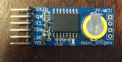
real time clock

The first thing to do is get a real time clock working on your Arduino. There are many real time clock modules out there on the internet and many guides on how to use them. You might even already have one built in. Make sure you have a reasonably accurate one. Go forth and do that. Make sure you can get the current time out of the RTC module and set the time.

Why do we need a real time clock for an Arduino controlled telescope?

This is the core of the telescope GOTO project. Your PC/planetarium software is only going to tell the Arduino the coordinates of the target in celestial coordinates. The Arduino GOTO code needs to work out where in the sky to point given the location, date and time. To do this, it needs to start by you getting an understanding of Local Sidereal Time.

Celestial coordinates for the Arduino GOTO.

You need to understand how RA/Dec works, what LST means and what Hour Angle means. There are countless pages on the Internet covering these subjects, but here is my take on it.

Celestial objects and the sky in general requires a coordinate system so we can locate targets in a format which is universally understood. On the surface of the Earth we use latitude and longitude. In the sky we use Right Ascension (RA) and Declination (dec). RA & Dec are analogous to latitude and longitude. RA is the East/West component (i.e. longitude) and declination is the north/south component (i.e. latitude). 90 degrees declination is roughly where Polaris is, and 0 degrees declination is on the celestial equator – an imaginary line running roughly where the zodiac constellations are.

RA, for reasons which will become clear, is measured in hours. 0h to 23h 59mins. One hour is about 15 degrees. But where does RA start? We are familiar with longitude starting at Greenwich in the UK and increasing eastwards. RA also has a zero point. It is somewhere near Pisces. It has all sorts of names and meanings which do not concern us.

So we have our coordinate system. Stars and other non-solar-system bodies can have a permanent RA/Dec which everybody can understand. Taking Regulus in Leo as an example, it is at RA = 10h 08m and Dec = 12deg 27’. Right now, 10am on the 27th July from the UK I would have to point fairly low in the east. But by later today I would need to point down in the west. Furthermore, if I lived in a different location the position in the sky would be completely different. If I lived on the equator then Regulus would be much higher in the sky.

Regulus’ RA & Dec never changes (well not much) but its apparent position in the sky various with time and location.

Enter local sidereal time (LST). Every day, from your location, the RA zero point (that spot in Pisces) will transit – i.e. be in the sky exactly south of here. Clearly this varies with the time of year and the time of day. So we define 00:00 LST to be this instant. The calculation of LST from current date, time and location is a complex approximation, found here. Please note that LST will usually appear very different to your normal local time. Right here and now it is 14:57 local time, but my LST clock says 10:14.

Now examine a telescope. The telescope must be equatorially mounted. The RA axis of the mount points at Polaris. Clearly we can move this shaft to any angle. This is called Hour Angle. If I wanted to point the telescope due south I would put the axis at zero degrees (Hour Angle zero). If I wanted to point at the horizon east or west, then it is +/- 90 degrees.

The hour angle of a star (as discussed above) depends on time and location. LST also depends on time and location. The RA of a star is fixed. The final magic bit of the puzzle is to say that the required Hour Angle of the telescope mount RA shaft is, HA = LST- RA.

For example, Regulus is at RA = 10h 08m. When the local sidereal time (LST) is 10:08, Regulus will be due south, transiting. So we would drive our telescope RA axis to the zero degrees position.

In a few hours’ time, when my LST clock reads, say 15:26, I perform the sum, HA = LST-RA = 15:26-10h 08m = +05:18. We are still in “time” here. Convert to degrees x15 so Ha = 79.5 degrees. Again, this is the angle at which I place my RA axis.

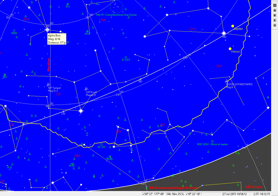
Here is another example

south viewAt the bottom in the taskbar you can see the RA of arcturus (which is due south) is almost the same as the LST
That is all, all that there is to it.

There is declination as well, but (pier flips aside) that is just a case of setting the telescope declination axis to the same value in degrees as the objects declination.

So getting back to the Arduino

As I said above, the first thing to do add LST calculation to the Arduino. Before you can do this you will also have to program it to remember your location (either store latitude and longitude in EEPROM or get it from a GPS). Whilst you are at it, store the elevation although you only need that for refraction calculations, which your planetarium software should handle.

Then write code to calculate LST, either work it out yourself or follow my LST instructions.

Now we must turn to ASCOM

Next I recommend getting the ASCOM toolchain up and running. You need a copy of Visual Studio, and you need to download the developer components from the ASCOM website. I’m not going to waffle on about creating ASCOM drivers, I covered it all in my video here and here.

Create a telescope driver and link it up to talk to your Arduino via serial. Now start implementing some of the simple properties such as location and time. You will need to invent your own protocol for talking between ASCOM and the Arduino. Nobody else is going to see it.

Here is an early stage of my system.

Some properties in the driver must be implemented, and the ASCOM Conformance checker can be used to validate the driver.

My suggestion is that you code some variables into Arduino which hold the current and target coordinates, and implement the various ASCOM slew methods and properties and basically make yourself a pretend telescope. Just the Arduino and the real time clock – not connected to a telescope mount. You will probably also want to implement the Altitude and Azimuth ASCOM driver properties – although it is up to you whether you do this in the ASCOM driver or in the Arduino. I did it in the Arduino.

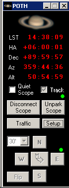
You should then be able to connect your planetarium software to your new ASCOM driver and use GOTOs to slew around the sky. The ASCOM hubs, e.g. POTH are very good for this.

poth

Extend the Arduino side of it so it is calculating the shaft angles required as well – i.e. implement all the HA = LST-RA stuff.

ASCOM kitchen sink window.

ASCOM tell you not to provide a popup window in your driver that has loads of buttons and the kitchen sink.

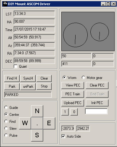
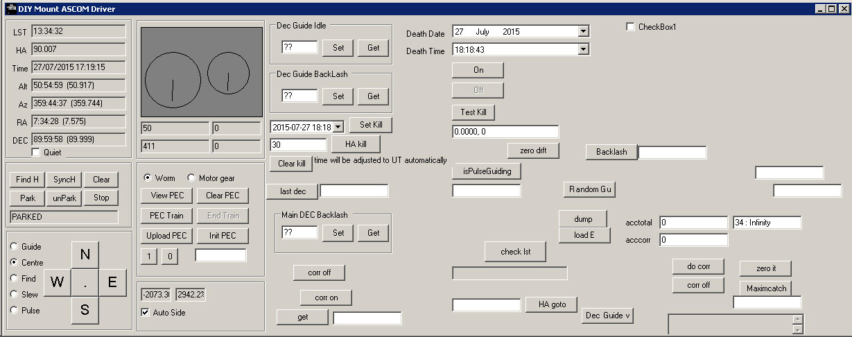
However, the only thing on your PC connected to Arduino is the ASCOM driver, and you are doing to want to be able to push a lot of non-standard commands down to the Arduino alongside the ASCOM stuff, so add a control panel window to the driver which you open when the connect property of the driver is set. You can put whatever you like on this window. Mine looks like this, although hidden from view (on the right) you can see all many of experimental test buttons and so forth.

mount control panel windowmount control panel window expanded

Now you are going to need some motors

I don’t really care if you are using stepper motors or DC motors with encoders. I will talk about “encoder ticks” but this could quite easily mean stepper steps if you are doing it that way.

The most important function of a telescope mount is to track the sky at the correct speed. This means keeping the Declination axis still and slowly and smoothly moving the RA axis. By now you have probably come across the concept of a sidereal day, 23.9344696 hours. The RA Axis of our telescope mount needs to move at 1 revolution every 23.9344696 hours. So the next task is to go and setup your gears, motors, power supplies and controllers and get the Arduino running the motors, and advancing the motor smoothly at the correct speed for sidereal tracking.

How do we know the correct motor speed for sidereal tracking? In my case, I have 360 tooth worm gears. So I need to turn my worm once every 239.34 seconds . My motor has a 30:1 reduction output gearbox. So the motor spindle needs to turn at one rev every 7.98 seconds, or about 7.5rpm. My motor has 2048 tick encoder, so the motor needs to run such that the encoder is doing 1 tick every 3.8 microseconds. Or about 256 ticks per second.

But that is just my situation. Your motors and gears will be different. The goal is to implement a PID controller or somesuch that runs the motor at the correct speed for sidereal tracking.

The choice of motor and gears is critical. In my case the motor has a max speed of around 5000rpm. This is about 83 revs per second. The output gearbox, 30:1, moves at 2.7 revs per second. Therefore my max slew speed is 2.7 degrees per second (360 tooth worm remember). Motor and gear choice is a balance between being able to run at sidereal speed and having a healthy maximum slew speed.

At the slewing end, anything slower than 2 degrees per second slewing is a bit tedious. At the tracking end… well, you need the encoder resolution sufficient to run the motor smoothly at the low tracking speed. Or in the case of stepper motors, you can’t exactly advance the scope at one step per second as this will appear a little jerky.

The telescope mount will spend a lot of time running at sidereal speed… so it is important to get right.

Hook up your motor to the telescope mount and manually (PUSH-TO) move the scope to point at a star… if you’ve got the sidereal tracking correct, then the star won’t move much.

Drive the motors for manoeuvring

Now you have your Arduino running the motors smoothly at sidereal rate, you need to add the ability to run the motors a little faster – for making small adjustments to the scope position, e.g. to centre a star. You can implement 256 different speeds for the user to selected from if you wish, but don’t. Meade had this one right, you only need 4 speeds. Slew speed, find speed, centre speed and guide speed. For me, slew is top speed, find rate is about 64x sidereal and centre is about 24x sidereal. Guide is half sidereal.

These speed options are more than enough for anybody.

Or do it completely differently – it is entirely up to you.

You will have to dig into the parts of the ASCOM telescope mount driver that deal with Axis rates and MoveAxis methods. There are plenty of ASCOM client tools which allow you access to NSEW controls to steer the telescope around the sky.

It isn’t quite this simple of course. If I am sidereal tracking and need to move north at FIND speed, then I need to power up the Declination motor, but I can’t stop the sidereal rate on the RA axis. Also, if the RA axis starts moving and is then stopped, it must not stop entirely, but smoothly transition back to sidereal rate.

Moving to the right shaft angle: GOTO.

Once motors and gearing are decided and setup, it is a case of simple arithmetic to move the shafts to any particular angle. Using the bit of celestial coordinates information about, it is then straightforward to implement GOTO. Well, nearly. What happens is something like this.

  • First the real time clock module is consulted by the Arduino to get the current local time.
  • Arduino then uses the known longitude of the observatory to calculate the local sidereal time.
  • Knowledge of the target RA is then used to find the required Hour angle.
  • The required hour angle and declination are then used to calculate the required shaft angles.
  • There are around 80000 encoder ticks per degree – so we can find the required encoder tick target
  • Signals are then sent to slew the motors at full speed until the required encoder tick count is reach, slowing down and stopping at the correct place

However, the “correct place” is constantly changing. If the slew takes 10 seconds, the initially calculated position will be wrong by a couple of arc minutes. So you have to keep re-evaluating LST and the required shaft angles and moving a bit more until the correct place is reached.

Flipping the pier

Oh this is the worst part. Go and read the ASCOM documentation about pier flips and side-of-pier calculations. It will make your head hurt. Unless you hav a fork mount, in which case forget it.

As you will know if you own a German equatorial mount then the declination axis sometimes has to be rotated 180 degrees. What this means to us it that depending on that part of the sky you are looking at, you may need your declination shaft angle to be 180 degrees out otherwise when you move from east to west you will end up pointing at the ground.

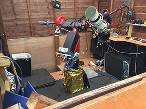
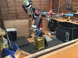
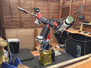
Also remember that for every position in the sky there are two possible configurations for the mount. We are most familiar with this when doing a meridian flip. E.g. I can have the scope like this

mount facing south in one solution Or like this mount facing south in another solutionAnd both are pointing at the same azimuth, but the shaft angles are all 180 degrees out.
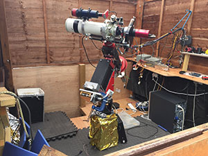
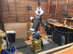
Both are perfectly valid. More amusingly we can point somewhere over in the west with either of these configurations

valid west solution for telescope bad west solution for telescopeOne is less useful than the other. Most mounts would crash doing the right hand version. When doing a GOTO you need to automatically choose the shaft angles that yield the correct angles for the better of the two solutions.
However, consider this telescope position.

avoiding flipYou don’t want to have the mount pointing like this as a result of a normal GOTO, but in some situations it is actually desirable. On my driver window above you can see a little “Autoside” tickbox. This allows to me override the automatic selection of shaft angles and GOTO in to this odd position.
The purpose is to avoid a meridian flip. For example, at 9pm in early January, Orion is in the south-east and about 2 hours from transit. If I “wind” the mount back into the above position, I can start imaging Orion in the southeast, and keep tracking it without stopping for a meridian flip until it sets at about 4am.

I find this an extremely useful feature.

Correcting the GOTO

The next thing to do is implement a syncing function to refine the GOTO. This is all about the ASCOM driver methods SyncToCoordinates() etc.

Normally after performing a GOTO we aren’t pointing exactly where we want. Perhaps we GOTO a bright star, once the GOTO has finished, the user adjusts the position of the scope with the move buttons to the exact right position. The scope will now think we are pointing at a slightly different RA/Dec. Then we tell our planetarium software to “sync to target”. This tells the scope where it is actually pointing. The scope them must calculate offsets between where it thinks it is pointing and where it has been told it is pointing. These offsets are used for all future gotos until the next sync amends them.

Far more usefully, instead of a bright star, we simply take a photo and plate solve, and then use our imaging software (e.g. Maxim DL) to sync the scope to the solved position.

Parking

A Parking function is in the ASCOM driver. This simply slews the scope a previously defined Park position, and turns off the motors.

Autoguiding

Look up the pulseguide function in the ASCOM driver.

Future work

Other features I have implemented

  • Emergency shut down
  • Shutdown timer for unattended imaging
  • Periodic error correction of the transmission gears (PEC)
  • Local monitoring of temperature and humidity.
  • Finding a home position (using Hall sensors)

After that you can do more or less whatever you wish!

Source: Arduino Projects: How to write a GOTO telescope mount controller

Stepper motor

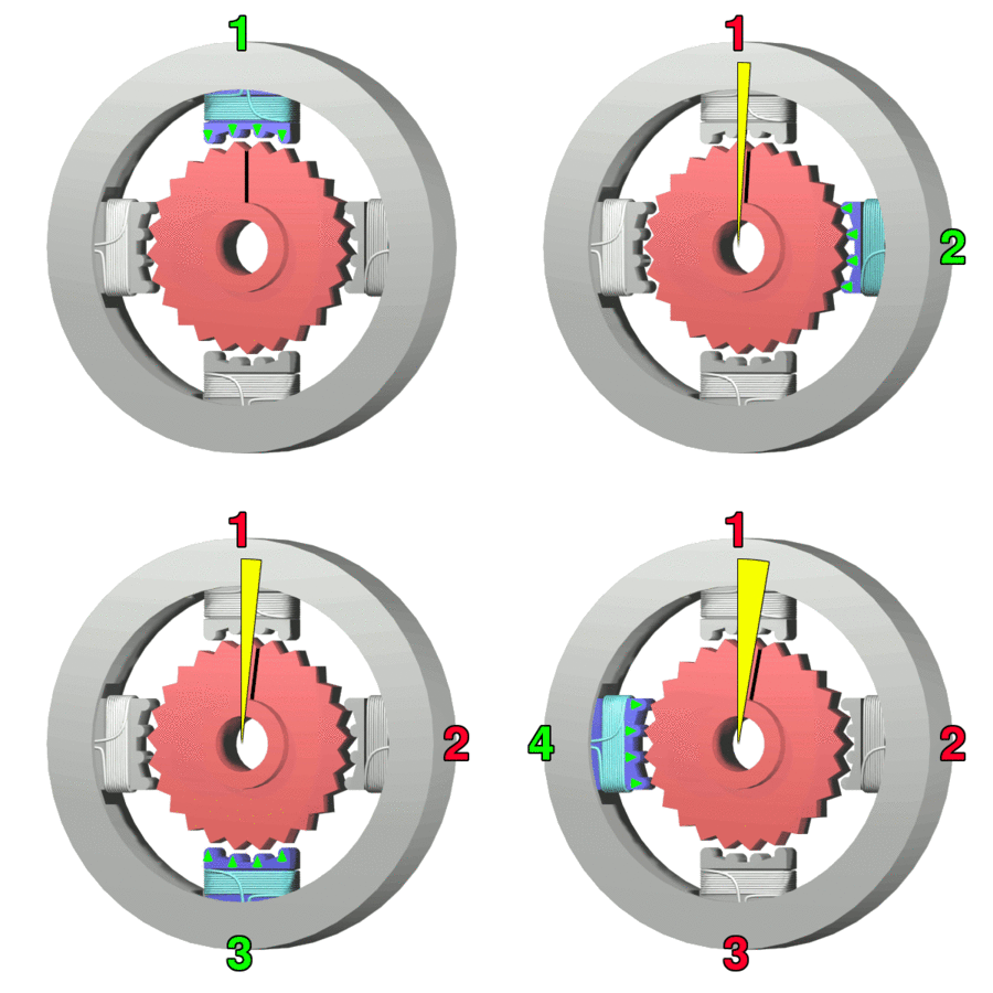
A stepper motor or step motor or stepping motor is a brushless DC electric motor that divides a full rotation into a number of equal steps. The motor’s position can then be commanded to move and hold at one of these steps without any feedback sensor (an open-loop controller), as long as the motor is carefully sized to the application in respect to torque and speed. Switched reluctance motors are very large stepping motors with a reduced pole count, and generally are closed-loop commutated.

Source: Stepper motor – Wikipedia