tty – root profile error – Ask Ubuntu
 Jovan Stosic
Jovan Stosic
Jovan Stosic
Jovan Stosic
Jovan Stosic
I purchased few days ago this 315mhz rf kit http://www.ebay.ie/itm/121038336534?ssPageName=STRK:MEWNX:IT&_trksid=p3984.m1497.l2649#ht_3567wt_1163 for a small robot i am building for my son. I was planning to record the signal the key fob sends with the famous rc-switch library(https://code.google.com/p/rc-switch/) and then with those values do my stuff. Buttt i am not getting anything to the the serial monitor. In the past i used a 433mhz transmitter and it worked just fine but now i am just not getting anything. Any ideas – directions?
Jovan Stosic
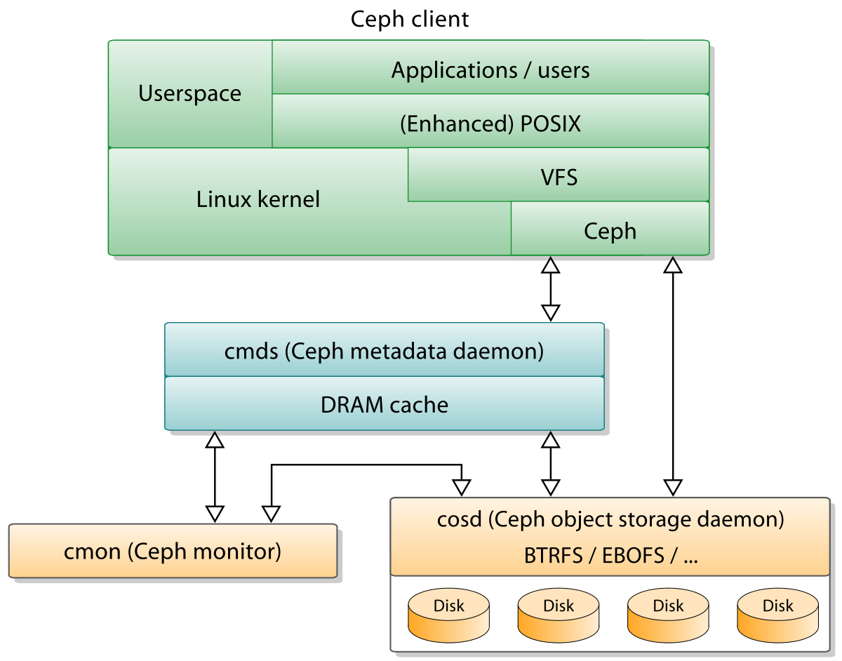
In computing, Ceph, a free-software storage platform, implements object storage on a single distributed computer cluster, and provides interfaces for object-, block- and file-level storage. Ceph aims primarily for completely distributed operation without a single point of failure, scalable to the exabyte level, and freely available.
Ceph replicates data and makes it fault-tolerant,[6] using commodity hardware and requiring no specific hardware support. As a result of its design, the system is both self-healing and self-managing, aiming to minimize administration time and other costs.
On April 21, 2016, the Ceph development team released “Jewel”, the first Ceph release in which CephFS is considered stable. The CephFS repair and disaster recovery tools are feature-complete (snapshots, multiple active metadata servers and some other functionality is disabled by default).[7]
Source: Ceph (software) – Wikipedia
Jovan Stosic
Prusa i3 (i3 stands for third iteration of the design) is the latest design by me. There are countless variations of the design and it became a staple of 3D printing with tens, if not hundreds, of thousands units world wide. You can build simple one for couple hundred dollars or you can chip in more and get the state of the art 3D printer, it’s all up to you.It’s open functional design allows for quick maintenance. For example if our DumbExtruder™ (LOL) breaks you can clean it in couple seconds! This makes i3 great workhorse 3D printer for your business. Not to mention the ability to upgrade the printer as you wish without manufacturer forcing you to buy a new model! Future-proof FTW!
Jovan Stosic
Xen Project (pronounced as /ˈzɛn/ /prˈɒdʒɛkt/) is a hypervisor using a microkernel design, providing services that allow multiple computer operating systems to execute on the same computer hardware concurrently. It was developed by the Linux Foundation and is supported by Intel.
The University of Cambridge Computer Laboratory developed the first versions of Xen. The Xen Project community develops and maintains Xen Project as free and open-source software, subject to the requirements of the GNU General Public License (GPL), version 2. Xen Project is currently available for the IA-32, x86-64 and ARM instruction sets.
Source: Xen – Wikipedia
Jovan Stosic
QEMU (short for Quick Emulator) is a free and open-source hosted hypervisor that performs hardware virtualization (not to be confused with hardware-assisted virtualization).
QEMU is a hosted virtual machine monitor: it emulates CPUs through dynamic binary translation and provides a set of device models, enabling it to run a variety of unmodified guest operating systems. It also can be used together with KVM in order to run virtual machines at near-native speed (requiring hardware virtualization extensions on x86 machines). QEMU can also do CPU emulation for user-level processes, allowing applications compiled for one architecture to run on another.
Source: QEMU – Wikipedia
Jovan Stosic
Kernel-based Virtual Machine (KVM) is a virtualization infrastructure for the Linux kernel that turns it into a hypervisor. It was merged into the Linux kernel mainline in kernel version 2.6.20, which was released on February 5, 2007.[1] KVM requires a processor with hardware virtualization extensions.[2] KVM has also been ported to FreeBSD[3] and illumos[4] in the form of loadable kernel modules.
KVM originally supported x86 processors and has been ported to S/390,[5] PowerPC,[6] and IA-64. An ARM port was merged during the 3.9 kernel merge window.[7]
A wide variety of guest operating systems work with KVM, including many flavours and versions of Linux, BSD, Solaris, Windows, Haiku, ReactOS, Plan 9, AROS Research Operating System[8] and OS X.[9] In addition, Android 2.2, GNU/Hurd[10] (Debian K16), Minix 3.1.2a, Solaris 10 U3 and Darwin 8.0.1, together with other operating systems and some newer versions of these listed, are known to work with certain limitations.[11]
Paravirtualization support for certain devices is available for Linux, OpenBSD,[12] FreeBSD,[13]NetBSD,[14] Plan 9[15] and Windows guests using the VirtIO[16] API. This supports a paravirtual Ethernet card, a paravirtual disk I/O controller,[17] a balloon device for adjusting guest memory usage, and a VGA graphics interface using SPICE or VMware drivers.
Jovan Stosic
Jovan Stosic
This post aims to be a complete guide for the popular RF 433MHz Transmitter/Receiver module. with the Arduino
Source: RF 433MHz Transmitter/Receiver Module With Arduino | Random Nerd Tutorials
Jovan Stosic
Kodi (previously known as XBMC), is a free, open source (GPL) multimedia player that originally ran on the first-generation Xbox, and now runs on Linux, OS X, Windows, Android and iOS. Kodi can be used to play/view the most popular video, audio, and picture formats, and many more lesser-known formats, including:
- Video – DVD-Video, VCD/SVCD, MPEG-1/2/4, DivX, XviD, Matroska
- Audio – MP3, AAC.
- Picture – JPG, GIF, PNG.
These can all be played directly from a CD/DVD, or from the hard-drive. Kodi can also play multimedia from a computer over a local network (LAN), or play media streams directly from the Internet. For more information, see the Kodi FAQ.
As of version 12, it can also be used to play and record live TV using a tuner, a backend server and a PVR plugin; more information about this can be found on the Kodi wiki.
Source: Kodi – ArchWiki
Jovan Stosic
I want to be able to click links in Thunderbird emails and have them open in Chromium (package name
chromium-browser). Instead, they open in Firefox.I have tried the following:
- xfce preferred applications (Chromium is not listed, so I had to hunt down the executable) — next time I run chromium, it complains that it is no longer the default browser.
- Telling Chromium to set itself as the default browser. Thunderbird opens links in Firefox.
- update-alternatives. It’s already listed as an alternative at the same priority as Firefox. The “open web browser” app menu item opens Chromium. Thunderbird opens links in Firefox.
I have looked through the entire preferences gui in Thunderbird (but not the advanced config editor yet) and seen nothing that mentions what browser to open links in.
Please note that this is not Google Chrome
Source: How do I make Thunderbird open links in Chromium? – Ask Ubuntu
Jovan Stosic
pinMode(), digitalRead(), digitalWrite(), analogWrite() work as usual.
Pin numbers correspond directly to the esp8266 GPIO pin numbers. To read GPIO2, call digitalRead(2);
All digital IO pins are protected from over-voltage with a snap-back circuit connected between the pad and ground. The snap back voltage is typically about 6V, and the holding voltage is 5.8V. This provides protection from over-voltages and ESD. The output devices are also protected from reversed voltages with diodes.
At startup, pins are configured as INPUT.
GPIO0-GPIO15 can be INPUT, OUTPUT, or INPUT_PULLUP.
GPIO16 can be INPUT, OUTPUT, or INPUT_PULLDOWN_16. It is also XPD for deepSleep() (perhaps via a small capacitor.)
Note that GPIO6-GPIO11 are typically used to interface with the flash memory ICs on most esp8266 modules, so these pins should not generally be used.
analogRead(A0) reads the value of the ADC channel connected to the TOUT pin.
ESP8266EX also integrates a generic purpose 10-bit analog ADC. The ADC range is from 0V to 1.0V. It is typically used to measure the voltages from the sensor or battery status. The ADC cannot be used when the chip is transmitting. Otherwise the voltage may be inaccurate. (From Expressif datasheet CH 8.5)

Pin interrupts are supported through attachInterrupt(), detachInterrupt() functions. Interrupts may be attached to any GPIO pin except GPIO16, but since GPIO6-GPIO11 are typically used to interface with the flash memory ICs on most esp8266 modules, applying interrupts to these pins are likely to cause problems. Standard Arduino interrupt types are supported: CHANGE, RISING, FALLING.
analogWrite(pin, value) enables software PWM on the given pin. PWM may be used on pins 0 to 15. Call analogWrite(pin, 0) to disable PWM on the pin. Value may be in range from 0 to 1023. 0 to 255 is normal on an Arduino board, as it’s an 8bit ADC, but ESP8266 is 10 bit so 1023 is full duty cycle.
The most usable pin functions are mapped to the macro SPECIAL, so calling pinMode(pin, SPECIAL) will switch that pin to UART RX/TX on pins 1 – 3, HSPI for pins 12-15 and CLK functions for pins 0, 4 and 5.
SPECIAL maps to:
You can activate any “FUNCTION” with pinMode(pin, FUNCTION1) for example.
Note: Func number 1-5 in Expressif table corresponds to FUNCTION 0-4 in SDK
http://bbs.espressif.com/download/file.php?id=442

ESP8266 has three modes of operation: SDIO mode, UART mode and FLASH mode. These are obtained by pulling three pins either high or low at bootup: GPIO15, GPIO0, GPIO2 according to this table:
0 Low
1 High
x floating
| MODE | GPIO15 | GPIO0 | GPIO2 |
|---|---|---|---|
| SDIO (BootSDCard) | 1 | x | x |
| UART (UploadCode) | 0 | 0 | x or 1 |
| FLASH (NormalRunning) | 0 | 1 | x or 1 |
Note :- GPIO2 It is considered safer to pull it high with a resistor on boot rather than leave it floating to avoid possible chip damage if pin is pulled high by your program but also see http://www.esp8266.com/viewtopic.php?f=6&t=3862&p=22524#p22524.
FLASH mode is when running the program. Take GPIO0 high or float or it will stall on first reset, intentional or not.
UART mode is how the code is uploaded to the chip and GPIO0 and GPIO15 must be low on boot to enter this mode.
SDIO mode is where the chip boots from an SD card. I don’t think this is available to us yet.
Note that there’s a special switch to swap UART0 RX/TX with UART0 CTS/RTS which is what systemuartswap does and is explained in http://bbs.espressif.com/viewtopic.php?f=7&t=22&p=54&hilit=system_uart_swap#p54:
#define FUNC_U0CTS    4
#define FUNC_U0RTS    4

void user_init(void) {
PIN_FUNC_SELECT(PERIPHS_IO_MUX_MTCK_U, FUNC_U0CTS);//CONFIG MTCK PIN FUNC TO U0CTS
PIN_FUNC_SELECT(PERIPHS_IO_MUX_MTDO_U, FUNC_U0RTS);//CONFIG MTDO PIN FUNC TO U0RTS
SET_PERI_REG_MASK(0x3ff00028 , BIT2);//SWAP PIN : U0TXD<==>U0RTS(MTDO) , U0RXD<==>U0CTS(MTCK)
......
}
Original func:
U0TXD⇒pin:U0TXD
U0RXD⇒pin:U0RXD
U0CTS⇒pin:MTCK
U0RTS⇒pin:MTDO
After pin swap:
U0TXD⇒pin:MTDO
U0RXD⇒pin:MTCK
U0CTS⇒pin:U0RXD
U0RTS⇒pin:U0TXD
This allows the MTDO and MTCK to be connected to a microcontroller as UART tx/rx. The bootup info will be output via U0TXD pin, but after start-up, the UART0 will output data via MTDO and receive via MTCK.
kolban asserts: “The device writes to UART1 by itself in certain circumstances. First, when you flash the device, the data received is apparently also written to the TX pin of UART1 (GPIO2). Second, the ‘debug’ code in the device writes its output to UART1.”
If anyone has a reference for this please post it on the thread http://www.esp8266.com/viewtopic.php?f=6&t=3862&p=22524#p22524
GPIO1, which is also TX, is wired to the blue LED on many devices. Note that the LED is active low (connected to Vcc and sinks through the chip to ground) so setting a logical value of 0 will light it up. Since GPIO1 is also the TX pin, you won’t be able to blink the LED and perform Serial communications at thew same time unless you switch TX/RX pins.
When using a GPIO as output (i.e. to drive something such as an LED) it is important to note that the maximum output current is 12mA. (IMAX=12mA per Espressif datasheet) If you try and output more current than that, you run the risk of damaging the device. Since many LEDs are able to draw 20mA you should adjust your current limiting resistor to be 12mA or less. Using https://en.wikipedia.org/wiki/LED_circuit – R=(Vout-Vled)/I so (3.3V-1.8Vred) at 12mA = 125Ω min for a red LED.