Source: Arduino – AttachInterrupt
Engineering and technology
ESP8266 – DHT11 issue
By JayEmSydney – Fri May 27, 2016 12:59 am
I have recently run into issues with the DHT11. It turns out that the issue is the time that a call to pinMode takes in the DHT11 library. In a small program pinMode returns as fast as 2.5-5 microseconds. In my large program it can take as long as 37 microseconds!!! This causes the code to overrun the timing at the start of the sequence when telling the DHT11 to start sending data. A call to expectPulse(LOW) finds that the line has already gone high and returns 0 immediately. The mainline code interprets this as a timeout (which also returns 0 from expectPulse()).
My initial response was to edit the code to change some of the timings but it was hard to make it correct for both the small program (fast execution) and large program (slow).
However, I recently discovered that the ESP8266 has fast instruction RAM (IRAM) and slower flash storage. I suspected that the routines are being pushed out of IRAM & consequently slowing down quite badly. So I modified the DHT.CPP to include a directive to ensure that the two timing critical routines (DHT::read and DHT::expectPulse) were both run from IRAM…
CODE: SELECT ALL
boolean __attribute__((section(".iram.text"))) DHT::read(bool force) { ...

and

uint32_t __attribute__((section(".iram.text"))) DHT::expectPulse(bool level) {...
So far, no more problems! ![]()
By JayEmSydney – Fri May 27, 2016 8:56 pm
Post-script to my previous post – Whilst the code above does seem to fix the problems with the DHT11, it doesn’t restore the timing of the pinMode function to the fastest that I’ve seen (2.5 microseconds). It takes it down to about 16 microseconds which is fast enough to fix the problem.
I’m not entirely sure why pinMode is so slow, except that I’m using the paho PubSub client and the slow down is definitely connected with subscribing to topics. Whether this pushes some code out of the fast memory, or if there is some interaction going on, I don’t know. But if I remove all but one subscription call – 2.5 microseconds again!!
Odd.
I have been running an ESP8266-01 with a DHT11 for several weeks continuously with no problems, using teh library with the 3rd option DHT dht(DHTPIN, DHTTYPE, 15); but not sure if that made a difference.
Now I am trying to use a DHT11 on a Wemos D1.
Did nt use the 3rd option so just DHT dht(DHTPIN, DHTTYPE);
That worked without problems till I started adding to the program, making it slightly bigger. Then most of my readings failed (someone else in this thread described that too). It is OK in the first reading after start, but then the majority fails. Adding parameter ’15’ did not make a difference. When I run the slightly smaller program again…. works like a charm, bigger one doesnt
JayEmSydney wrote:……
However, I recently discovered that the ESP8266 has fast instruction RAM (IRAM) and slower flash storage. I suspected that the routines are being pushed out of IRAM & consequently slowing down quite badly. So I modified the DHT.CPP to include a directive to ensure that the two timing critical routines (DHT::read and DHT::expectPulse) were both run from IRAM…
CODE: SELECT ALLboolean __attribute__((section(".iram.text"))) DHT::read(bool force) { ...
and
uint32_t __attribute__((section(".iram.text"))) DHT::expectPulse(bool level) {...
So far, no more problems!
That helped indeed a lot. Before maybe 1 out of 50 readings would NOT generate a failed to read error, and after your change about 1 out of 20 WOULD generate an error. Still not ideal, but a lot better
– See more at: http://www.esp8266.com/viewtopic.php?f=32&t=4210&p=57237#p57237
Going nutty trying to get a DHT11 to work – Everything ESP8266
hard reset (un-plug USB on Wemos D1) reboots into configuration mode · Issue #64 · marvinroger/homie-esp8266 · GitHub

Owner
marvinroger commented on Apr 14, 2016
This is not an expected behavior. I guess the USB is connected to a computer, can you try with a charger? 
Contributor
jpmens commented on Apr 14, 2016
@sumnerboy12 I’ve just checked for you with the Homie version I’m running (Github pull pre 1.3.0): works as advertised, i.e. I can cold-boot (also via USB) and device starts publishing. Contributor
jpmens commented on Apr 14, 2016
@sumnerboy12 it just occurs to me that I didn’t configure via WiFi, instead preferring to write the config directly to the file system. (Note the commented SPIFFS.format()which you might need to uncomment.)https://gist.github.com/jpmens/d674114400c1dd7ba169403afb7d1ea1
Owner
marvinroger commented on Apr 14, 2016
@jpmens if configuring via the API is successful, then the FS is in the exact same state as if it was written directly during flash or using your sketch, so this should not be the issue here. Owner
marvinroger commented on Apr 14, 2016
Can you also post the debug output on the Serial monitor? There should be a message like ✖ Cannot mount filesystem. dholmen commented on Apr 14, 2016
I’ve had the same problem with at least one of my NodeMCU’s. There are no error messages in the serial monitor, it just looks like a normal config mode boot.  sumnerboy12 commented on Apr 14, 2016
Yes same here – there is nothing appearing on serial when it reboots
into configuration mode. I will need to have more of a play this
evening, but it is good to know this is not expected behaviour. I will
endeavour to do some more digging and report back here.On 15/04/2016 9:00 AM, dholmen wrote:
I’ve had the same problem with at least one of my NodeMCU’s. There are
no error messages in the serial monitor, it just looks like a normal
config mode boot.—
You are receiving this because you were mentioned.
Reply to this email directly or view it on GitHub
#64 (comment)Owner
marvinroger commented on Apr 14, 2016
The configuration mode is started when the Config.load()method returns false. If you look at the sources, you will see that everywhere false is returned, there is a log message, I don’t see any codepath where this would not be the case. I might be wrong!sumnerboy12 commented on Apr 15, 2016
after some debugging with @jpmens we discovered this was caused by Windows it seems – as soon as I unplug/re-plug the Wemo into my Windows laptop it resets the device back into config mode – if I flash the Wemo, un-plug and plug into a wall wart, it boots up fine. This can be repeated with no issues. As soon as I plug the Wemo back into my Windows laptop, it is reset and reverts back to config mode.
Very odd, but I don’t think this is a Homie issue so I will close this issue.
Contributor
jpmens commented on Apr 15, 2016
I’m confident @marvinroger knows a tonne more about these devices than we do, and can maybe say whether he’s encountered similar resets with Windows and/or whether it’s a known Windows driver issue. Owner
marvinroger commented on Apr 15, 2016
WeMos D1 boards embed a CH340G USB serial chip. I have a NodeMCU v2, which embeds a CP2102 chip, and I had this problem once or twice, so it is way more stable. Maybe try to install this driver, if not already done. I am sorry, I can’t help more on this! But yes, definitely not an Homie issue.
sumnerboy12 commented on Apr 15, 2016
updating to that driver seems to have resolved it – thanks a million @marvinroger!!! Owner
marvinroger commented on Apr 16, 2016
Awesome! You’re welcome!  DavidStacer commented on Apr 16, 2016
I had this problem too on a Wemos D1-mini. Updating the driver did not solve it. To diagnose this and see all the message, I connected up another USB serial port adapter. Then connected the RX from the second serial board to the D1-mini TX pin and tied GND to the serial board. I then used Termite terminal program to monitor the serial traffic.
I changed the default Homie baud rate to 74880 – that is ESP8266 default boot baud rate. This allowed me to see the ESP8266 boot up messages too.
Now I could see all of the messages. When I pulled the main D1-mini USB cable and plugged back in, the majority of the time I would see:
• SSL: no
• OTA
• Enabled: no
Flagged for reset by pin
Device is in a resettable state
Configuration erased
↻ Rebooting in config modeMy theory:
When pinMode(this->_interface->reset.triggerPin, INPUT_PULLUP); is executed, the onboard D1-mini USB Serial adapter may not let the GPIO0 pin go high right a way. If you look on the D1-mini schematic, the RTS is connected to the GPIO0 pin via resister and NPN transistor. I’m speculating that the PC driver needs to give it a command to change (high or low don’t know which).Placing a delay(50); after the Homie.setup() and before the Homie.loop(); seemed to solve the problem too but I didn’t like that as a solution.
Looking much deeper into the bounce code for the switch I found the default state is set to 0 meaning the switch is closed – requesting configuration mode. In Bounce::attach I changed it to be state=1; as the default.
I have cycled the D1-mini with the USB cable many times and it seems to have fixed the problem of going into configuration mode without pressing and holding the switch.
Owner
marvinroger commented on Apr 16, 2016
@DavidStacer so what can I do at Homie’s level? There is no way to programmatically set the default value of the state in Bounce2. So changing this line to state = 1;fixes the issue for you?Maybe I can add this in the in troubleshooting in the docs?
DavidStacer commented on Apr 16, 2016
Changing that line did fix it for me because Bounce attach() sets the default to 0 but 1 would be a better default for this application. When _handleReset call is made to _resetDebuncer.read() it just returns the current Bounce::read() value. The current state is still low because update() has only been called one time, so we really are not getting a debounced reading but just the initial reading.
I think its hard to fix in Homie but maybe don’t call the _resetDebuncer.read() until the DEFAULT_RESET_TIME has passed since boot up but that is just another way of delaying. I guess we are delaying the time before getting the switch value vs. holding up the rest of the program.
I will test out that idea and see if it works.

Contributor
clough42 commented on Aug 8, 2016
I was having a similar problem and came across this issue. The solution wasn’t immediately clear, so I’m summarizing to help others who also get here and are confused: If your WeMos D1 Mini loses its configuration when you plug it into your computer with USB, it is probably erroneously detecting the RTS/DTS wiring in the WeMos as a request to reset and delete the configuration.
You can disable the reset trigger completely with Homie.disableResetTrigger() and it will stop deleting the config. If you want the reset trigger behavior, you may be able to move it to another pin. I have not attempted this.
 NikosVlagoidis commented on Sep 26, 2016
I have the same problem but only whenever i plug it on my power bank. the problem occurred after many uses of the power bank. any thoughts? NikosVlagoidis commented on Sep 27, 2016
actually Homie.disableResetTrigger() worked for my pc the first time but now does not work anywhere and i don’t know what to do
GPIO16 WOES – ESP8266 Developer Zone
glTF
glTF (GL Transmission Format) is a runtime asset delivery format for GL APIs: WebGL, OpenGL ES, and OpenGL developed by the Khronos Group 3D Formats Working Group and first announced at HTML5DevConf 2016. glTF is an efficient, interoperable asset delivery format that compresses the size of 3D scenes and models, and minimizes runtime processing by applications using WebGL and other APIs. glTF also defines a common publishing format for 3D content tools and services.
https://en.m.wikipedia.org/wiki/GlTF
160mm vs. 180mm rotor Pro/Cons?- Mtbr.com
nd here.
Otkriven misteriozan objekt u našem Sunčevom sustavu – Dnevnik.hr
Control DC and Stepper Motors With L298N Dual Motor Controller Modules and Arduino
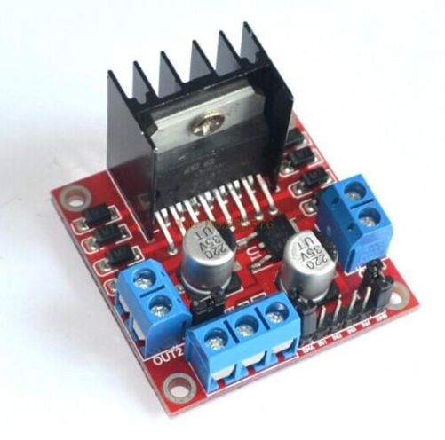
You don’t have to spend a lot of money to control motors with an Arduino or compatible board. After some hunting around we found a neat motor control module based on the L298N H-bridge IC that can allows you to control the speed and direction of two DC motors, or control one bipolar stepper motor with ease.The L298N H-bridge module can be used with motors that have a voltage of between 5 and 35V DC. With the module used in this tutorial, there is also an onboard 5V regulator, so if your supply voltage is up to 12V you can also source 5V from the board. So let’s get started!
Source: Control DC and Stepper Motors With L298N Dual Motor Controller Modules and Arduino
Wiznet W5100 (Ethernet Shield) Buffer Question.
So it looks like there is 8Kb of internal RX buffer on the W5100 chip… so how does one deal with reading the data faster than its coming in? If I don’t read it fast enough or too fast what happens? How do you flush the buffer on chip via client.flush()? I suspect it’s FIFO. I’m running into a situation where I am getting 8k of data posted to me and it looks like the data is being “clipped” … guess the buffer is getting filled.Looking at the W5100.c file there is mention of how the memory channels are allocated… anyone know how it’s setup to work? Full 8kb or less?
Arduino Modules – L298N Dual H-Bridge Motor Controller
Quick and simple start guide for using and exploring an L298N Dual H-Bridge Motor Controller module with an Arduino.The model in the example I am using is from Ebay. Materials needed: L298N Dual H-Bridge Motor Controller module (various models will work) Male to Female jumper wires An Arduino, any flavor. A DC power supply, 7-35vA motor that is the correct voltage for your power supply used.
Source: Arduino Modules – L298N Dual H-Bridge Motor Controller
DIY Stepper Controller using Arduino | Night Sky in Focus
My first version of a stepper controller uses a 555 timer chip and a 74LS194 shift register. The tracking rate is controlled by the 555 timer chip through a resistor and a capacitor. By changing the resistance and capacitance values, the tracking rate also changes. A variable resistor is used to speed up and slow down the rotation of the stepper. Since the timing signals are controlled by analog components, the tracker suffers from issues related to the tracking rate. It usually requires ‘tracking rate adjustment’ (to match the movement of the sky) at the start of an imaging session. While it has served me for four years and used it to image some interesting targets, it is clear that an upgrade is needed.
Upon learning some basics about Arduino, I immediately saw the potential to use it as a controller for a stepper motor, the kind of motor used in devices that require precise motion control such as in many telescope mounts. I started looking at some excellent tutorials on the Internet and was able to build the simple stepper controller featured in this article.
The main advantage of using a microcontroller is that it makes it possible for the stepper controller to keep a far accurate tracking rate, unlike my previous controller that changes tracking rate with the slightest change in ambient temperature. Since it is digital, there is no need for a re-calibration at the start of every imaging session. Buttons can be placed to allow easy adjustment of the tracking speed such as to speed up or slow down the tracking rate momentarily, for easy adjustment. LEDs can be used as status indicators (e.g., current step rate).
After a few months, I have finally built a fairly simple yet reliable stepper controller that can be used to drive very small trackers, or even more advanced ones such as a telescope. And since it is built with an Arduino, it is possible to add some upgrades to it in the future.
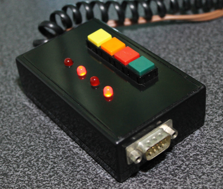
Controller for equatoral trackers such as a telescope mount with stepper motor
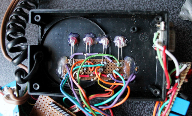
Removing the cover reveals the circuit board for the stepper driver. This circuit sits on top of the Arduino, much like a DIY shield (a circuit board that you can attach readily to an Arduino by stacking it on top of it, through the connecting pins.)
Stepper controller with the DIY stepper driver circuit.
Dismantled, you can clearly see the Arduino board on the left (there are many versions of an Arduino board, in this particular project, I have used what is called an Arduino UNO). You can see the connecting pins that run vertically on the board’s left and right sides. The pins connect the Arduino to the Stepper Driver (center). The Stepper Driver is a board that holds L293D chip and some PC817 optical isolators. Some LED lights were left on the board which could come handy during troubleshooting. Also visible is some sort of a relay circuit and its connector (right), to allow a GPUSB (some kind of a module that allows a computer to talk to my telescope mount) to control the DIY Stepper Controller for autoguiding purposes (it’s a completely optional feature that I decided to include as it may come handy in the future). The use of a GPUSB, however, will be discussed in a separate article.
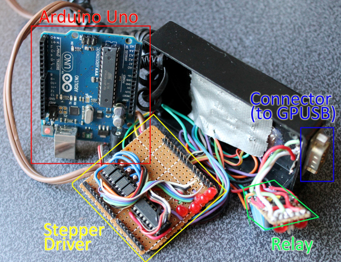
Components of the stepper controller. Only the Arduino Uno and the Stepper driver will be discussed in this article. The Relay and the Connector (for GPUSB) to enable a computer to send guiding signals to the stepper controller (for autoguiding purposes) will be discussed in a separate article.
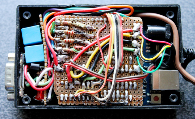
Here you can see the circuit board for the LED lights and the four push-button switches.
The circuit for the LED lights and the push-buttons.
To build this DIY Stepper Controller, you will be needing some basic understanding of electronic circuits. The diagram below illustrates how the parts will be put together.
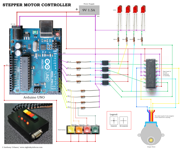
To view a larger image, click here. Circuit diagram for the Stepper Motor Controller. An Arduino Uno is used to provide pulses for the L293D H-bridge through optional PC817 opto-isolators. The circuit can drive both bipolar and unipolar steppers (operated in bipolar mode).
The Arduino board requires what is called a ‘sketch’. A screenshot of the sketch used in this DIY stepper controller is shown in the following photo. As you may have noticed, it is composed of lines of text with a set of instructions in it. It is a ‘program’ that you upload to the Arduino board to let it know what to do. This program is uploaded by connecting the Arduino board to a computer through a USB connection, using the Arduino Software. Learn more about Arduino. Once you are familiar with some basics, you will be able to understand how to use the sketch below.
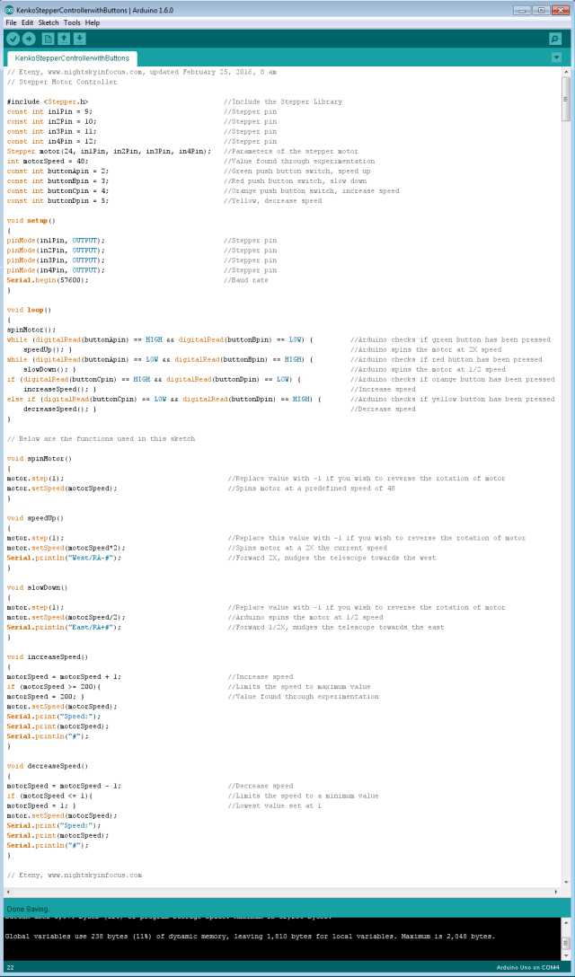
To view a larger image, click here. Script for the Arduino stepper motor controller. For inquiries about the sketch, please send an email to eteny@nightskyinfocus.com.
If the sketch above seems too complicated, you can try uploading a simpler sketch that can be used to spin the motor (note that this sketch does not read the buttons, it only spins the motor).
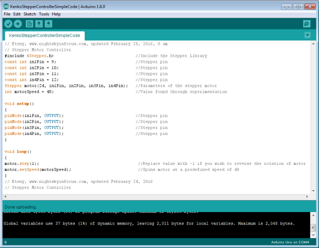
To view a larger image, click here. Script for the Arduino stepper motor controller. For inquiries about the sketch, please send an email to eteny@nightskyinfocus.com.
Once you’ve finished building the DIY Stepper Controller circuit above and uploaded the sketch to the Arduino board, you should see some blinking lights indicating that your controller is up and running and ready to track the skies!
Arduino stepper motor controller for a telescope mount.
This page is a work-in-progress. In future posts, I will describe an advanced application of the tracker such as enabling the Arduino stepper controller to receive commands from a computer through a serial connection, and perform automatic tracking error corrections (autoguiding) with a program running on a computer, such as PHD Guiding.
Visit this page for captured images and future upgrades on this project. Clear skies!

To view a larger image, click here. A 240-second test image to determine the tracker’s accuracy. The image was taken a focal length of 900 mm from a city with severe light pollution using a filter-modified Canon 450D DSLR. Tracking was guided using PHD2 Guiding software, a modified Logitech 4000 web camera, and a 400 mm focal length guide scope.
Related link:
Stepper Motor Controller (Analog)
Improvised Clock Drive Project
Source: DIY Stepper Controller using Arduino | Night Sky in Focus
As soon as I unplug the USB cable and re-connect, the device goes back into configuration mode.