Introduction
ESP8266 is a low cost wifi enabled chip. It comes in a variety of module types and can be programmed in a variety of ways.
All modules make GPIO0 and GPIO2 accessible. Most modules, other than ESP8266-01, also make GPIO15 accessible. These GPIO’s control how the module starts up and as such require special handling if they are to be used at all. GPIO6-GPIO11 also require special treatment as described below
ESP8266 Programming Tips (espcomm failed)
When programming the ESP8266 using the Arduino IDE (see ESP8266-01 Wifi Shield) you sometimes (often) get an error messages in the Arduino IDE like
esp_com open failed
error: Failed to open COM33
error: espcomm_open failed
error: espcomm_upload_mem failed
In that case follow these steps to get it working:-
-
Check you have ESP8266 board selected in the Arduino Tools menu
-
Check you have selected a COM port in the Arduino Tools menu
-
Power cycle the ESP8266 with GPIO0 grounded (clean power application, see below)
-
If 3) does not fix it, unplug the USB cable from the computer wait few secs and plug it back in
-
If 4) does not fix it, uplug USB cable from PC, close Arduino IDE, open Arduino IDE, plug USB cable back in.
When you apply power to the ESP8266, after grounding GPIO0, make sure it is applied cleanly. Don’t jiggle the connection. The ESP8266 led should just come on and stay on without any flashes.
Flash GPIO pins – GPIO6 to GPIO11
Most ESP8266 boards have a flash chip connected to some or all of GPIO6-GPIO11. Most programs use flash memory, as well as RAM, so unless you specifically make sure your code only runs from RAM, you can’t use these pins for other purposes.
The exact number of pins used in the range GPIO6 to GPIO11 depends on the type of flash hardware used on your module. Quad IO uses 4 lines for data (6 pins total) for up to 4 times the speed of standard. Dual IO uses 2 lines for data (4 pins total) Standard uses a single line for data ( 3 pins total).
Unless you know exactly what your board requires, you are best to just ignore GPIO6 to GPIO11 and do not refer to them from your code.
GPIO0, GPIO2 and GPIO15 pins
These pins determine what mode the chip starts up in.
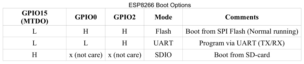
For normal program execution GPIO0 and GPIO2 need to be pulled up to Vcc (3.3V) and GPIO15 needs to be pulled to GND, each with a resistor in the range 2K to 10K resistor. A 2K resistor gives better noise immunity. OLIMEX uses 2K resistors SparkFun uses 10K resistors. I use 3K3 resistors.
The settings of these inputs is only checked during the power up (or reset) of the chip. After that the pins are available for general use, but as discussed below their use is restricted by these external pull up/down resistors.
Using GPIO0, GPIO2 and GPIO15 as Outputs
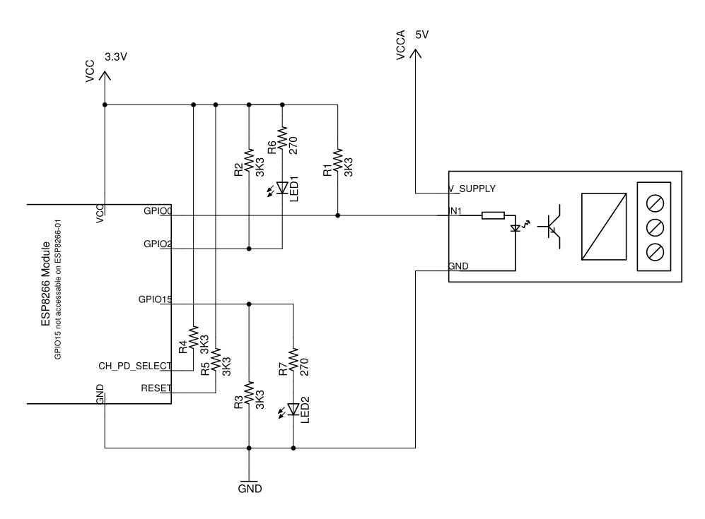
As noted above, these pins will already have a resistor connected to either VCC (GPIO0 and GPIO2) or GND for GPIO15. This determines how any external device, like a relay or led+resistor, must be connected. For GPIO0 and GPIO2, an external relay must be connected between VCC and the pin so that it does not interfere with the action of the pull up resistor. Conversely an external relay connected to GPIO15 must be connected between GND and the pin so that is does not interfere with the action of the pull down resistor.
To activate the external device, GPIO0 or GPIO2 must be driven LOW (Active LOW) while GPIO15 must be driven HIGH (Active HIGH).
The schematic below shows how to use GPIO0 and GPIO2 and GPIO15 as outputs. This circuit includes the necessary pullup/pulldown resistors as well. Note the 5V relay module driven by GPIO0 is opto-isolated and has a separate common connection for the input. It is important that the 5V VCCA voltage is not applied to the ESP8266 pin.
Using GPIO0, GPIO2 and GPIO15 as Inputs.
Using these pins as inputs is a bit tricky. As noted above on power up, and during reset, these pins must be pulled up or down as required to have the ESP8266 module start up in normal running mode. This means, in general, you cannot just attach an external switch to the these pins because at power up you usually cannot guarantee the switch will not be pulling the input to ground and so prevent the module from starting correctly.
The trick is to not connect the external switch directly from the GPIO0 or GPIO2 to GND but to connect it instead to another GPIO pin which is driven to ground (as an output) only after the ESP8266 starts up. Remember, when used as outputs, the GPIO pins provide a very low resistance connection to either VCC or GND depending on whether they are driven HIGH or LOW.
Here only GPIO0 and GPIO2 will be considered. Using this method you can get one (1) addition input using these two (2) GPIO’s.
A similar method can be used for GPIO15 by using another GPIO pin to connect its switch to +VCC, but this does not gain an extra input, you might as well just use the other GPIO pin directly as an input.
The circuit below uses the ESP8266-01 module as an example. Without using this trick, the ESP8266-01 does not have any free pins to use as an input if you are already using pins RX/TX for a UART connection.
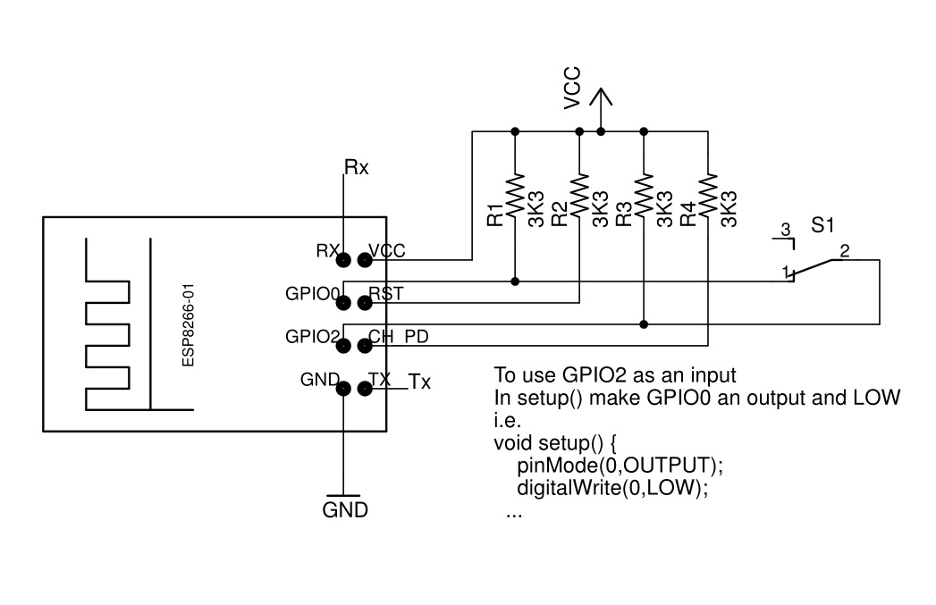
Since the sketch’s setup() method is only run after the ESP8266 module starts up, it is safe to make GPIO0 output LOW then and so provide a ground for S1 connected to GPIO2. You can then use digitalRead(2) elsewhere in your sketch to read the switch setting.
Conclusion
This short note shows how to used GPIO0, GPIO2 and GPIO15 as outputs and how to use get an extra input using GPIO0 and GPIO2 together.