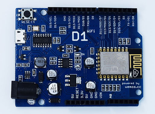
In this example we will create a basic webserver example using our Wemos, it will connect to your Wifi network and then you will navigate to a URL and a basic page will appear. This page will display 2 links , one will switch on an led connected to D5 and the other option will switch the led off.
Month: March 2017
Programming the ESP8266 WeMos-D1R2 Using Arduino Software/IDE
In this Instructable I will guide you through the steps needed to install, configure and program the WeMos-D1R2 board using the Arduino IDE.
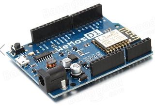
WeMos-D1R2 is an ESP8266-12 based WiFi enabled microprocessor unit on a Arduino-UNO footprint. That means the board looks and works (in most cases) like an UNO. Apparently several shields, sensors and output devices that are manufactured for the Arduino platform will work on the WeMos-D1R2 with the added advantage of builtin WiFi.
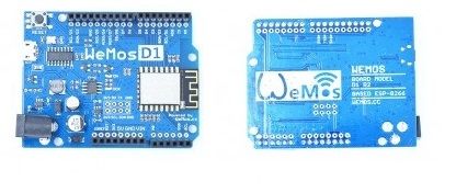
There are two WeMos boards in the market.If you are not careful you will end up with a D1 Board which is an older version. You have to make sure you have the current version of the board WeMos-D1R2. I bought my WeMos-D1R2 from Banggood, I believe it is a Hong Kong based online retailer. The quality of the product is good and has a short delivery time, about two weeks to the US. They carry the genuine WeMos-D1R2. There are several older model WeMos-D1 being sold as WeMos-D1R2 to unsuspecting customers by several other vendors.
You will find several similarities between this Instructable and my previous one – Programming the ESP8266-12E using Arduino software/IDEbecause of the fact that the ESP8266-12 is the foundation of the WeMos-D1R2 board. In some cases I have copied and pasted the complete steps.
Step 1: Differences Between the I/O Pins.
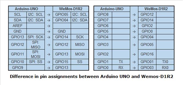
Though the Arduino UNO and the WeMos-D1R2 are similar, there are a few differences in their pin assignment. The above illustration provides the mapping of the pins. In some situations programs written for the UNO will need to be modified a little to the proper pin assignments of the WeMos-D1R2. More on this when we write our first sketch.
Source: Programming the ESP8266 WeMos-D1R2 Using Arduino Software/IDE
The correct way to plug in a buzzer?
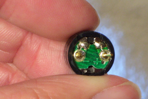
I’m writing a tutorial for newbs (also as a newb) that describes how to play music using an Arduino and CEM-1203 buzzer. The one thing that I need to confirm is how do I plug it in? Right now I have negative plugged into ground, and this was confirmed in IRC chat. I just wanted a second opinion just to be sure. With a buzzer, does it really matter what side plugs into ground? It has worked for me both ways without exploding… so far.
How to Use a Buzzer (or Piezo Speaker) – Arduino Tutorial
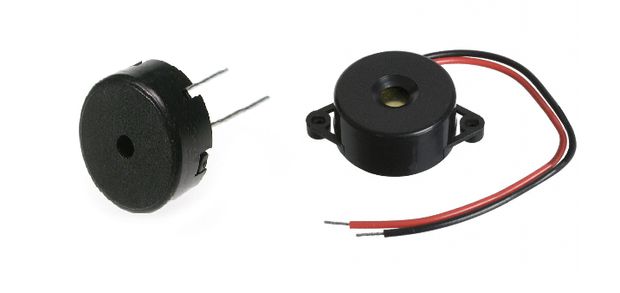
In this tutorial you will learn how to use a buzzer or piezo speaker with Arduino. Buzzers can be found in alarm devices, computers, timers and confirmation of user input such as a mouse click or keystroke.You will also learn how to use tone() and noTone() function.So, let’s get started!
Source: How to Use a Buzzer (or Piezo Speaker) – Arduino Tutorial
esp8266 on wifi serial board and Arduino Uno board – Stack Overflow
I bought esp8266 with serial wifi wifi card I connect RX to TX; TX to RX; VCC to VCC; GRD to GRD; I cant communicate with the board not if program mode and not in UART mode; the reset do nothing.
the red led on the board is on.
I connected the wifi serial to Arduino uno board. try to upload sketch i got the following error:
warning: espcomm_sync failed
error: espcomm_open failed
error: espcomm_upload_mem failed
Any help or guides will help me to solve the issue.
Source: esp8266 on wifi serial board and Arduino Uno board – Stack Overflow
Compare Home Controllers – HomeSeer Home Automation Systems
Each HomeSeer smart home controller is designed to address specific needs and budgets. The chart below includes a listing of the most popular products and technologies. A more complete listing of supported smart home products and technologies may be found on our plug-ins page. For questions or for help selecting the best system for your needs, please contact us directly!
Source: Compare Home Controllers – HomeSeer Home Automation Systems
nScope | a lab for every laptop by nLabs — Kickstarter
Antonio Caldara
Antonio Caldara (1670 – 28 December 1736) was an Italian Baroque composer.
Caldara was born in Venice (exact date unknown), the son of a violinist. He became a chorister at St Mark’s in Venice, where he learned several instruments, probably under the instruction of Giovanni Legrenzi. In 1699 he relocated to Mantua, where he became maestro di cappella to the inept Charles IV, Duke of Mantua, a pensionary of France with a French wife, who took the French side in the War of the Spanish Succession. Caldara removed from Mantua in 1707, after the French were expelled from Italy, then moved on to Barcelona as chamber composer to Charles III, the pretender to the Spanish throne (following the death of Charles II of Spain in 1700 without any direct heir) and who kept a royal court at Barcelona. There, he wrote some operas that are the first Italian operas performed in Spain. He moved on to Rome, becoming maestro di cappella to Francesco Maria Marescotti Ruspoli, 1st Prince of Cerveteri. While there he wrote in 1710 La costanza in amor vince l’inganno (Faithfulness in Love Defeats Treachery) for the public theatre at Macerata.
With the unexpected death of Emperor Joseph I from smallpox at the age of 32 in April 1711, Caldara deemed it prudent to renew his connections with Charles III – soon to become Holy Roman Emperor Charles VI – as he travelled from Spain to Vienna via northern Italy. Caldara visited Vienna in 1712, but found Marc’Antonio Ziani and Johann Joseph Fux firmly ensconced in the two highest musical posts. He stopped at the Salzburg court on his return journey to Rome, where he was well received (and to which he subsequently sent one new opera annually from 1716 and 1727). In 1716, following the death the previous year of Ziani and the promotion of Fux to Hofkapellmeister, Caldara was appointed Vice-Kapellmeister to the Imperial Court in Vienna, and there he remained until his death.
Caldara is best known as a composer of operas, cantatas and oratorios. Several of his works have libretti by Pietro Metastasio, the court poet at Vienna from 1729.
Source: Antonio Caldara – Wikipedia
Installing and Building an Arduino Sketch for the $5 ESP8266 Microcontroller
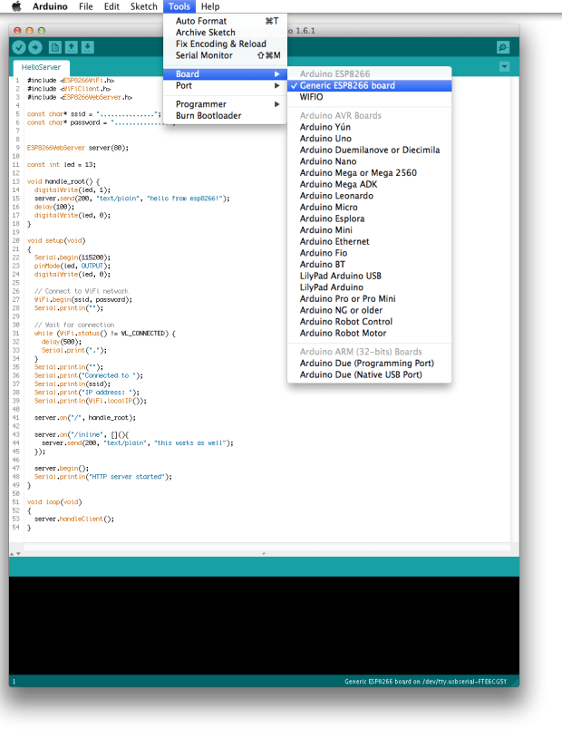
Custom build of the Arduino IDE with support for the ESP8266 chip and the esptool programmer.
Part 2 of a 3-post series on the new ESP8266 microcontroller
From our look at the $5 ESP8266 WiFi microcontroller and the new Arduino-compatible development environment that’s just been released, let’s get to work testing it out.
Installation of the custom build of the Arduino IDE really couldn’t be simpler. I’m on a Mac, and at that point it comes down to downloading the pre-built binary release from GitHub. The custom binary will live quite happily alongside your existing stock Arduino development environment — in fact, as well as the ESP8266 build, I think I’ve got six or seven other versions of the environment installed at the moment, with version numbers ranging from 1.0.x up to to latest 1.6.x build.
However, despite it being manageable, having a whole separate environment installed isn’t actually necessary. One of the things that the new 1.6.x release of the Arduino environment introduced was much more simplified support for adding and managing new boards.
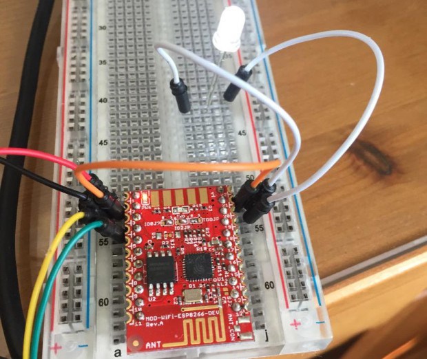
Blinking an LED using an Arduino sketch and a MOD-WIFI-ESP8266-DEV board. (Credit: Sandeep Mistry)
Which is exactly what Sandeep Mistry has now done with the ESP8266. Installation is almost as simple as before — download it and move the esp8266com folder included in the release inside the hardware folder of your Arduino sketchbook directory.
Wiring up the ESP8266 Module
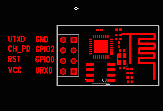
The pin out for the header block of the ESP-01 module
As I mentioned before, probably the most common breakout board you’ll come across for the ESP8266 is the ESP-01. Now unfortunately while the ESP-01 module has a standard spaced header block on one end, the pin out is rather inconvenient when dealing with breadboards. Because of the way the pins are laid out, you can’t just plug the module directly into a breadboard, you’re going to have to break out some jumper cables.
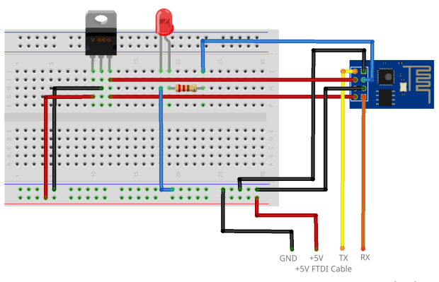
You’ll need to connect the VCC pin to a +3.3V supply, and the GND pin to ground. The board’s RX should be connected to the TX from your computer, and the board TX should be connected to the RX from your computer.
Additionally, to enable the board, you’ll need to pull the CH_PD pin high to +3.3V, and to allow you to upload your sketches you need to put the ESP8266 into bootloader mode by pulling the GPIO_0 pin low and toggling power to the board.
The two easiest methods to attach the board to your computer, so you can load your Arduino sketch onto the ESP8266, are either to use an FTDI adaptor board — like the FTDI Friend — or a standard FTDI cable.
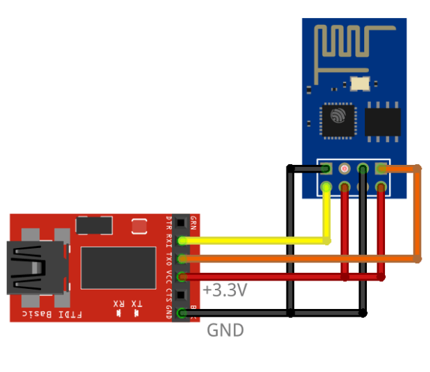
The ESP-01 wired up to an FTDI adaptor. The CH_PD pin is pulled up to +3.3V to enable the board, the GPIO_0 pin is pulled down to GND to enable firmware upload.
Just remember that, if you use a cable, you’ll also need to use a 3.3V regulator, or go ahead and build a voltage divider out of resistors, as the FTDI cable runs at 5V and the ESP8266 runs at just 3.3V.
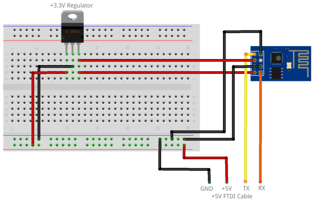
The ESP-01 wired up ready to be connected to a standard FTDI cable. The CH_PD pin is again pulled up to +3.3V to enable the board, whilst the GPIO_0 pin is pulled down to GND enabling firmware upload. Note the 3.3V regulator between the +5V input and the ESP-01 board.
After the sketch is uploaded you will need to remove the jumper between GPIO_0 and GND for things to work correctly.
Uploading the Sketch
The use case for the ESP8266 is controlling things via the network, it’s a classic Internet of Things platform. Let’s start off by doing some Internet of Things like things by flashing an LED on and off using the web. After all, if you can turn an LED on and off, you’re halfway to anywhere.
An LED attached to the free GPIO_2 pin of the ESP-01 board.
Go ahead and wire up your LED in the normal way to the spare GPIO pin, that’d be GPIO_2, and then open the Arduino IDE. Select “Generic ESP8266 Board” from the Tools → Boards menu, and the serial port your board is connected to from the Tools → Ports menu. Finally select “esptool” from the Tools → Programmer menu.
Now go to the File → Examples → ESP8266WiFi menu and load the “WiFiWebServer” sketch into an editor window. Replace the placeholders values in the script for “ssid” and “password” with the SSID and password for your WiFi network. Then hit the upload button.
If all goes well you you should see that it is “Uploading…” and then, after a while, that it is “Done uploading.” If you encounter an error then you should double check and ensure that the CH_PD pin is pulled high, and the GPIO_0 pin is pulled low. Then toggle the power on the board again to make sure it’s in bootloader mode. You should probably also check that RX is wired to TX, and TX to RX.
Now go ahead and open the Serial Monitor, remove the jumper between the GPIO_0 pin and GND, you toggle the power to the board again. If you do not toggle the power to the board at this stage, you sketch won’t be loaded.
However if all is still going well you should see something like this,
Connecting to Wireless Network
.......
WiFi connected
Server started
192.168.1.224
which tells you that the board has connected to the network, and rather crucially, what the board’s IP address ended up as when it negotiated its connection to the DHCP server.
The ESP-01 board running the “WiFiWebServer” example sketch
Now you can just go to your browser and use the endpoint http://gpio/1 to pull GPIO_2 high, and turn the LED on, or http://gpio/0 to pull GPIO_2 low, and turn the LED off. If you’re still connected to the Serial Console you should see something like this scroll by if you attempt to turn the LED on,
new client
GET /gpio/1 HTTP/1.1
Client disconnected
new client
GET /favicon.ico HTTP/1.1
invalid request
Here you can safely ignore the invalid request error message — that’s just your browser asking for the icon that accompanies the web pages its retrieving, it doesn’t necessarily expect a response — however at this point the LED connected to GPIO_2 should be on. Go ahead and try turning it off again.
If you succeed? Well, done. You’ve just replicated 90% of the functionality of a Philips Hue light bulb and built your first Internet of Things thing.
Now if you look closely at the video you might have noticed something odd about the ESP-01 board I’m using, it’s not connected via an FTDI adaptor, or a standard FTDI cable. Instead, I’m using a breadboard adaptor.
Why should I use the ESP8266?
While the ESP8266 can’t do everything you could do with an Arduino — for instance it only has one PWM pin that isn’t even exposed by the ESP-01 breakout board we’ve used here, you’d have to go looking for something like the Olimex board that Sandeep was using to get access to it — but for $5 it’s a bargain.
For $5 it doesn’t have to do the same amount as you can do with an Arduino, because at $5 you can afford to buy 5 or 6 of them for the price of a single Arduino board.
“This is inexpensive enough to be very much in the territory of ‘thousands of sensors-launched-out-of-a-cannon’-cheap.” — Brian Jepson
The ESP8266 was already well on its way to becoming — almost by stealth — one of the leading platforms for the Internet of Things. It’s super cheap, and super easy to work with, and it’s actually fairly easy — as such things go — to get your hands on, which makes a refreshing change.
However the arrival of Arduino compatibility is step change, suddenly the growing but still small community has opened their platform up to a much larger community. Suddenly there is a huge pool of people that know how to work with the board, and I think we’re going to see an explosion of projects and products that otherwise wouldn’t get made. Because suddenly we have our hands on a WiFi board, that we all know how to use, that’s almost cheap enough to throw away.
Get out your soldering iron and buy some boards, I’d love to see what you build with it. Especially if it involves cannons.
This is the second of three posts on the ESP8266 microcontroller. Part 1 of the series introduces the board, while the third part talks about creating a breadboard adaptorfor the ESP-01 breakout board.
Source: Installing and Building an Arduino Sketch for the $5 ESP8266 Microcontroller
Keira Knightley – Like A Fool
Keira Knightley – Like A Fool
arduino-info – Ethernet
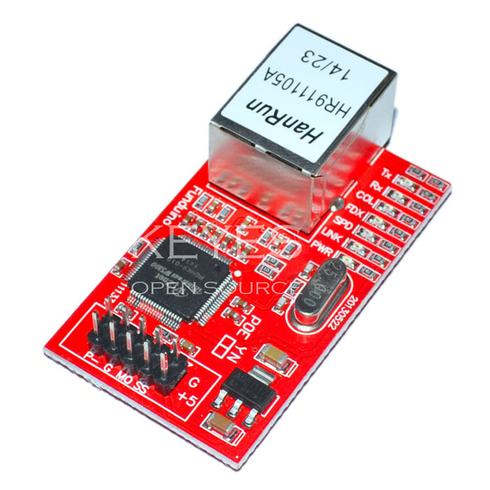 This module or an Ethernet Shield uses the W5100 chip which provides a set of TCP/IP protocols, MAC (Media Access) and PHY (Physical Interface) in one network chip, with support for the SPI bus interface.
The Ethernet Arduino IDE library that comes with the Arduino IDE is designed directly for W5100 and is supported on this product.
Your Arduino can be a Web Server with this brick! See an example HERE: But start out with “Your First Web Server” below.
NOTE: There are RED and GREEN versions of this module; they work and wire up the same..
There is on-board voltage regulation, so you can use 5-12V VCC input. The signal pins support both 3.3V and 5V levels.
The Ethernet Module has a standard RJ-45 connection, with an integrated line transformer. Another similar version exists with “Power Over Ethernet” connections that use the pins marked P+, P-, and G; this one does not use those.
NOTE: Most Ethernet Shields using the W5100 chip will work the same in the examples below.
W5100 Ethernet Module Information:
Source: arduino-info – Ethernet
Serial Peripheral Interface Bus
The Serial Peripheral Interface bus (SPI) is a synchronous serial communication interface specification used for short distance communication, primarily in embedded systems. The interface was developed by Motorola in the late eighties and has become a de facto standard. Typical applications include Secure Digital cards and liquid crystal displays.
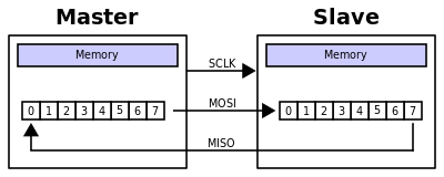
SPI devices communicate in full duplex mode using a master-slave architecture with a single master. The master device originates the frame for reading and writing. Multiple slave devices are supported through selection with individual slave select (SS) lines.
Sometimes SPI is called a four-wire serial bus, contrasting with three-, two-, and one-wire serial buses. The SPI may be accurately described as a synchronous serial interface,[1] but it is different from the Synchronous Serial Interface (SSI) protocol, which is also a four-wire synchronous serial communication protocol. But SSI Protocol employs differential signaling and provides only a single simplex communication channel.