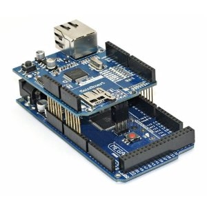
I’ve the ENC28J60 board up and running and I’m planning to use the webclient example to retrieve the weather forecast on regular basis using the following URL: http://gps.buienradar.nl/getrr.php?lat=52&lon=4
Month: March 2017
Using DHCP Mode with Arduino and Ethernet Shield – EMBEDDED LABORATORY
Most of the Arduino users found problem in using DHCP mode with Ethernet Shield, this tutorial will help to solve most basic problems when using using Arduino and Ethernet Shield in DHCP Mode.
Source: Using DHCP Mode with Arduino and Ethernet Shield – EMBEDDED LABORATORY
Ethernet shield hostname
Ethernet shield hostname
Source: Ethernet shield hostname
networking – How to see all computers connected to a network – Ask Ubuntu
I am in a LAN and there are 3 Ubuntu, 2 Kubuntu, 2 Windows XP and 2 Windows 7. What commands or tools are available to see what PCs are connected to the LAN that it shows the name of the PC and the IP. Similar to tools like Angry IP that show all PCs in a LAN.
Note that I do not know the IPs or names of the computers connected to the LAN. So the tool or command should look for them to.
Source: networking – How to see all computers connected to a network – Ask Ubuntu
EtherCard: EtherCard is a driver for the ENC28J60 chip, compatible with Arduino IDE.
Comparison of EDA software
DesignSpark PCB
DesignSpark PCB is a free electronics design software, (EDA software is a sub-class of computer-aided design (CAD) software.) Although there is no charge for the software, the user must register with the website to unlock the program and it displays advertisements which must be acknowledged before the user can begin working.
Source: DesignSpark PCB – Wikipedia
IR Communication – learn.sparkfun.com
IR Communication
CONTRIBUTORS: A1RONZO
Getting Started
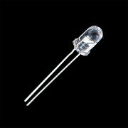
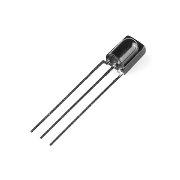
Transmitting IR LED (left) and receiving IR photo sensor (right)
IR, or infrared, communication is a common, inexpensive, and easy to use wireless communication technology. IR light is very similar to visible light, except that it has a slightlty longer wavelength. This means IR is undetectable to the human eye – perfect for wireless communication. For example, when you hit a button on your TV remote, an IR LED repeatedly turns on and off, 38,000 time a second, to transmit information (like volume or channel control) to an IR photo sensor on your TV.
This tutorial will first explain the inner workings of common IR communication protocols. Then we will go over two examples that will allow you to transmit and receive IR data using an Arduino. In the first example, we will read incoming IR data from a common remote control using the TSOP382 IR photo sensor. The next example will show you how to transmit data from an IR LED to control a common appliance, for example your home stereo.
All of the gritty signal processing is handled by a great Arduino library written by Ken Shirriff and allows you to easily send and receive IR data. For additional details on how the IR Arduino library works, see Ken’s blog here. Also, the code examples used in this tutorial are found in the examples directory in the library.
Here are some concepts that we will be covering in this tutorial.
IR Communication Basics
IR radiation is simply light that we cannot see, which makes it great for communication. IR sources are all around us. The sun, light bulbs, or any anything with heat is very bright in the IR spectrum. When you use your TV remote, an IR LED is used to transmit information to your TV. So, how does the IR receiver in your TV pick out signals from your remote among all of the ambient IR? The answer is that the IR signal is modulated. Modulating a signal is like assigning a pattern to your data, so that the receiver knows to listen.
A common modulation scheme for IR communication is something called 38kHz modulation. There are very few natural sources that have the regularity of a 38kHz signal, so an IR transmitter sending data at that frequency would stand out among the ambient IR. 38kHz modulated IR data is the most common, but other frequencies can be used.
When you hit a key on your remote, the transmitting IR LED will blink very quickly for a fraction of a second, transmitting encoded data to your appliance.
Each pulse is turned on and off at a frequency of 38kHz
If you were to hook an oscilloscope up to your TV remote’s IR LED, you would see a signal similar to the one above. This modulated signal is exactly what the receiving system sees. However, the point of the receiving device is to demodulate the signal and output a binary waveform that can be read by a microcontroller. When you read the OUT pin of the TSOP382 with the wave from above, you will see something like this:
By controlling the spacing between the transmitted modulated signals, the waveform can be read by an input pin on a microcontroller and decoded as a serial bit stream.
Below is conceptual view of how an IR transmitter receiver pair works.
Thanks to SBProjects.com for the gif and excellent IR resource!
An Arduino or other microcontroller can be connected to either end of the system to transmit data (left side) or receive data (right side).
Hardware Setup
For the hardware in this tutorial, you will need these parts:
- Arduino Uno
- IR LED
- TSOP382 IR Receiver
- Mini Push Button Switch
- 330Ω Resistors
- IR Keychain Remote or any IR remote that uses 38kHz modulation
You will be setting up two separate circuits both using an Arduino. The first example circuit uses a TSOP382 IR photo sensor to receive and demodulate the IR signal from a common remote control. The second example circuit uses an IR LED and current limiting resistor to transmit IR codes to a common appliance, for example a home stereo or TV.
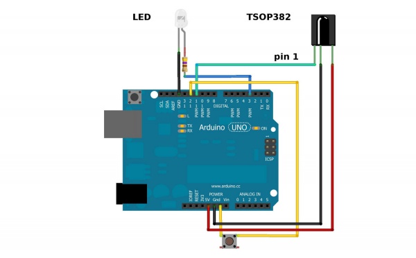
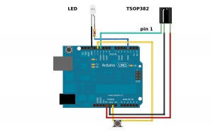
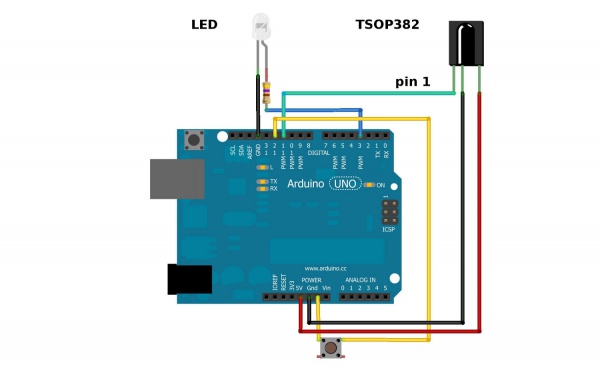
Here is the complete setup for connecting to an Arduino:
Hardware setup for both of the examples.
Be sure to connect your LED correctly! The long leg is positive and connects to the resistor, then to the Arduino’s output pin. The short leg is negative and is connected to ground (GND).
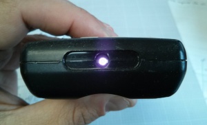
Also, you cannot see IR LED light with your eyes, since IR radiation is outside of the visible spectrum. However, most cellphone cameras can detect short wave IR and can see the LED faintly glowing.
When the LED is modulating at 38kHz, the LED should appear constantly lit, but dim.
Also, pay attention to the polarity of the TSOP382. Refer to the TSOP382 datasheet for the pinout of the sensor.
The current limiting resistor attached to the LED can have values down to 100Ω (40mA) for full power and longest range. If you use a larger value resistor, the LED won’t light as bright and your range will suffer. With a 330Ω resistor, you should be able to operate the IR LED across a dimly lit room.
Receiving IR Example
In this example, all you need is the TSOP382 IR receiver connected to an Arduino and a common remote control. The IR LED and button can stay connected, but you will not use it until the next example.
IR remote controls are as ubiquitous as their appliance counterparts. What if you could put all of those old remote controls to use in your next project? This example will show you how to read IR remote codes from any IR remote using the TSOP382 IR photo sensor and an Arduino. Once you can receive codes from individual button presses, your remote control and Arduino become a general purpose, short range, communication interface!
The first thing you need to do is install the IR Arduino library. Instructions on how to install an Arduino library can be found here.
After downloading the IR library, go to your Arduino project directory -> libraries -> IRremote -> examples -> IRrecvDemo -> and open the IRrecvDemo.ino. Upload the sketch to your Arduino.
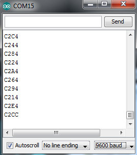
The sketch will automatically decode the type of remote you are using and identify which button on your remote is pressed. Open the serial port in the Arduino IDE at 9600 bps and hit different buttons on your remote.
Terminal window displaying random button presses on my remote. Different buttons show different codes.
When specific buttons are pressed, you can use the incoming values to do something else in your code, for example turn on and off a motor or LED.
The results from each button press can be found by calling the value() method:
results.valueYou can print the values to the terminal window:
Serial.println(results.value, HEX); //prints the hex value a a button pressOr you might need read the values to run a conditional statement:
if(irrecv.decode(&results)) //this checks to see if a code has been received
{
    if(results.value == 0xC284) //if the button press equals the hex value 0xC284
    {
        //do something useful here
    }
    irrecv.resume(); //receive the next value
}
Transmitting IR Example
This example uses both the LED and TSOP382.
In this example, your Arduino and an IR LED imitate an IR remote to control an appliance (TV, stereo, etc.). In order to control your appliance with the LED, you need to know what type of IR protocol your appliance uses. The easiest way to find this out is to have the remote that comes with the appliance. This example receives a remote key press with the TSOP382 IR photo sensor, copies the data, then sends it out of the IR LED.
The first thing you need to do, if you haven’t already, is to install the IR Arduino library. Instructions on how to insall an Arduino library can be found here.
After downloading the IR library, go to your Arduino project directory -> libraries -> IRremote -> examples -> IRrecord -> and open the IRrecord.ino. Upload the sketch to your Arduino.
After you have loaded the sketch, open the Arduino serial monitor to 9600bps. Point your remote directly at the TSOP382 and hit a button. You should see specific codes in the terminal window, corresponding to the button you hit on the remote.
Now, if you point the LED at your appliance and hit the push button that is connected to your Arduino, the code for the button press on your remote will be sent. Once you know which codes correspond to each button, you can create your own remote with the Arduino and IR LED.
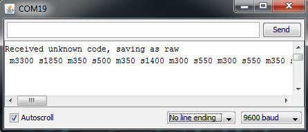
For example, in the image above, the circuit received and unknown code when the volume up button on my Panasonic remote was hit. The data bytes on the second line are the raw codes displayed as mark and space timings for the volume up command.
If you received an unknown code and want to send it, use this line in your Arduino sketch:
irsend.sendRaw(rawCodes, codeLen, 38);If you don’t have the appliance’s remote or if you are lucky enough to have a remote that uses a common protocol, then you can try the pre-loaded manufacturer codes from the IRSendDemo example in the IR Arduino library.
For example, if you have a Sony TV, and want the LED to turn your TV on and off, you can use this piece of code:
for (int i = 0; i < 3; i++)
{
    irsend.sendSony(0xa90, 12); // Sony TV power code
    delay(40);
}
Different appliance manufacturers use different protocols to send commands, this is why you have to define the manufacturer of the appliance to use this library. Also, note that the Sony command needs to be sent three times using a for loop. Every protocol will have its own intricacies. A good reference for un-official commands to common IR protocols can be found here.
There are a few common protocols the IR Arduino library supports. They are: NEC, Sony SIRC, Philips RC5, Philips RC6, and raw formats. Here are the methods you can use in your Arduino code for different manufacturers:
void sendNEC(unsigned long data, int nbits);
void sendSony(unsigned long data, int nbits);
void sendRC5(unsigned long data, int nbits);
void sendRC6(unsigned long data, int nbits);
void sendDISH(unsigned long data, int nbits);
void sendSharp(unsigned long data, int nbits);
void sendPanasonic(unsigned int address, unsigned long data);
void sendJVC(unsigned long data, int nbits, int repeat);
void sendRaw(unsigned int buf[], int len, int hz);
You will need to fill in the data and nibts fields with a information specific to the protocol you are using. More information on how use this feature can be found in the IR Arduino library blog post (see the ‘Details of the sending library’ section).
Note: The transmission range of the LED might not be optimal. Output pins on the Arduino can only source up to about 30mA of current. This means the LED cannot be driven to its full power of 50mA. This will result in a loss of transmission distance. If you want to drive an IR LED properly, consider using the Max Power IR LED Kit. However, a 330Ω attached to your IR LED should give about 10 feet of range.
power management – xset: unable to open display – Ask Ubuntu
for the longest time after about 5 minutes my screen would blank out. Now the screen will go blank after 5 minutes but then 2 seconds after that it will light up white and keep the laptop backlighting on. I didnt change any settings to my knowledge it just happened randomly after powering it on one day and has occurred since then.
I wish to resort back to blanking the screen out completely since i leave this computer on all the time and its hard to sleep with a huge white light all the time.
“xset dpms force off” just yeilds me —- xset: unable to open display “”
Source: power management – xset: unable to open display – Ask Ubuntu
tty – root profile error – Ask Ubuntu
rf-switch and 315mhz transmitter is a no go?
I purchased few days ago this 315mhz rf kit http://www.ebay.ie/itm/121038336534?ssPageName=STRK:MEWNX:IT&_trksid=p3984.m1497.l2649#ht_3567wt_1163 for a small robot i am building for my son. I was planning to record the signal the key fob sends with the famous rc-switch library(https://code.google.com/p/rc-switch/) and then with those values do my stuff. Buttt i am not getting anything to the the serial monitor. In the past i used a 433mhz transmitter and it worked just fine but now i am just not getting anything. Any ideas – directions?
Ceph (software)
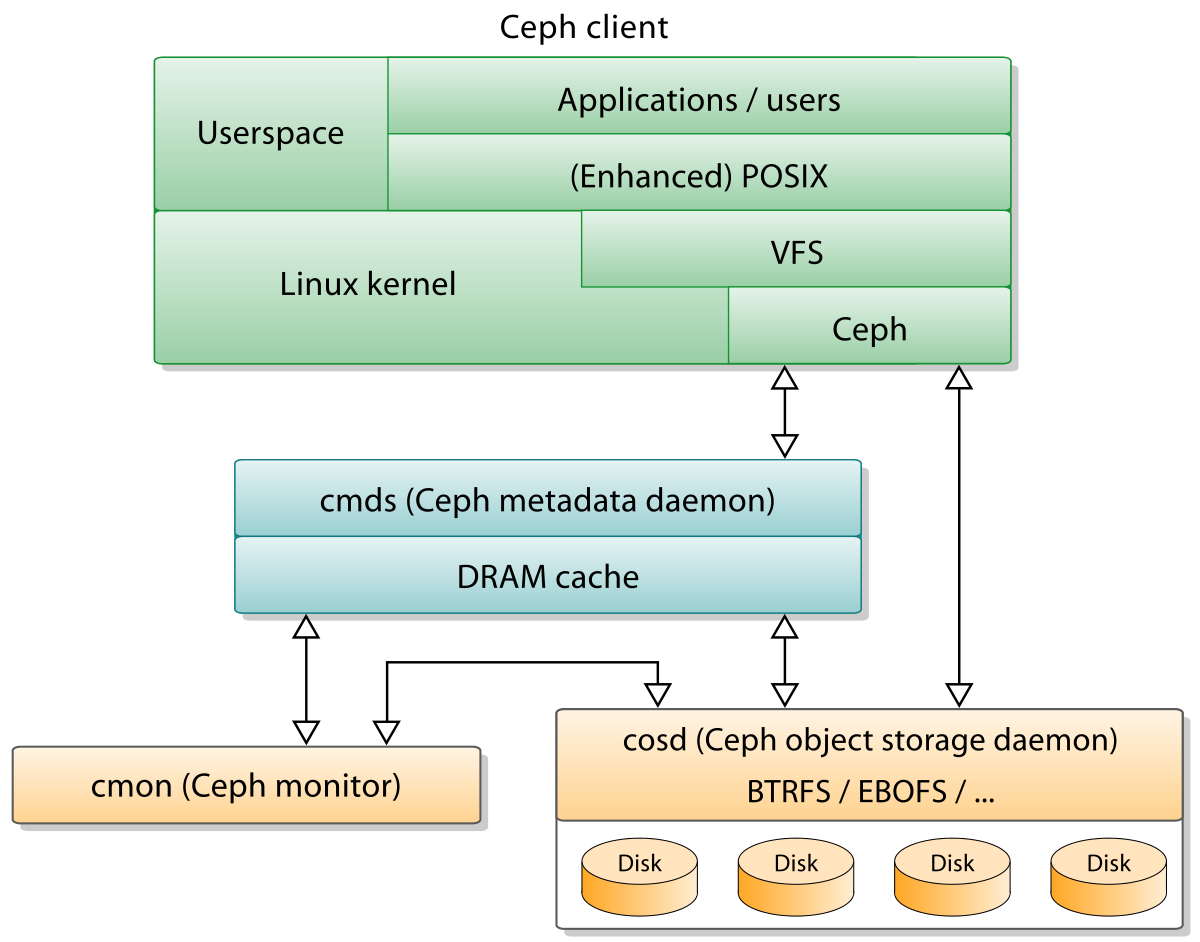
In computing, Ceph, a free-software storage platform, implements object storage on a single distributed computer cluster, and provides interfaces for object-, block- and file-level storage. Ceph aims primarily for completely distributed operation without a single point of failure, scalable to the exabyte level, and freely available.
Ceph replicates data and makes it fault-tolerant,[6] using commodity hardware and requiring no specific hardware support. As a result of its design, the system is both self-healing and self-managing, aiming to minimize administration time and other costs.
On April 21, 2016, the Ceph development team released “Jewel”, the first Ceph release in which CephFS is considered stable. The CephFS repair and disaster recovery tools are feature-complete (snapshots, multiple active metadata servers and some other functionality is disabled by default).[7]
Source: Ceph (software) – Wikipedia
